
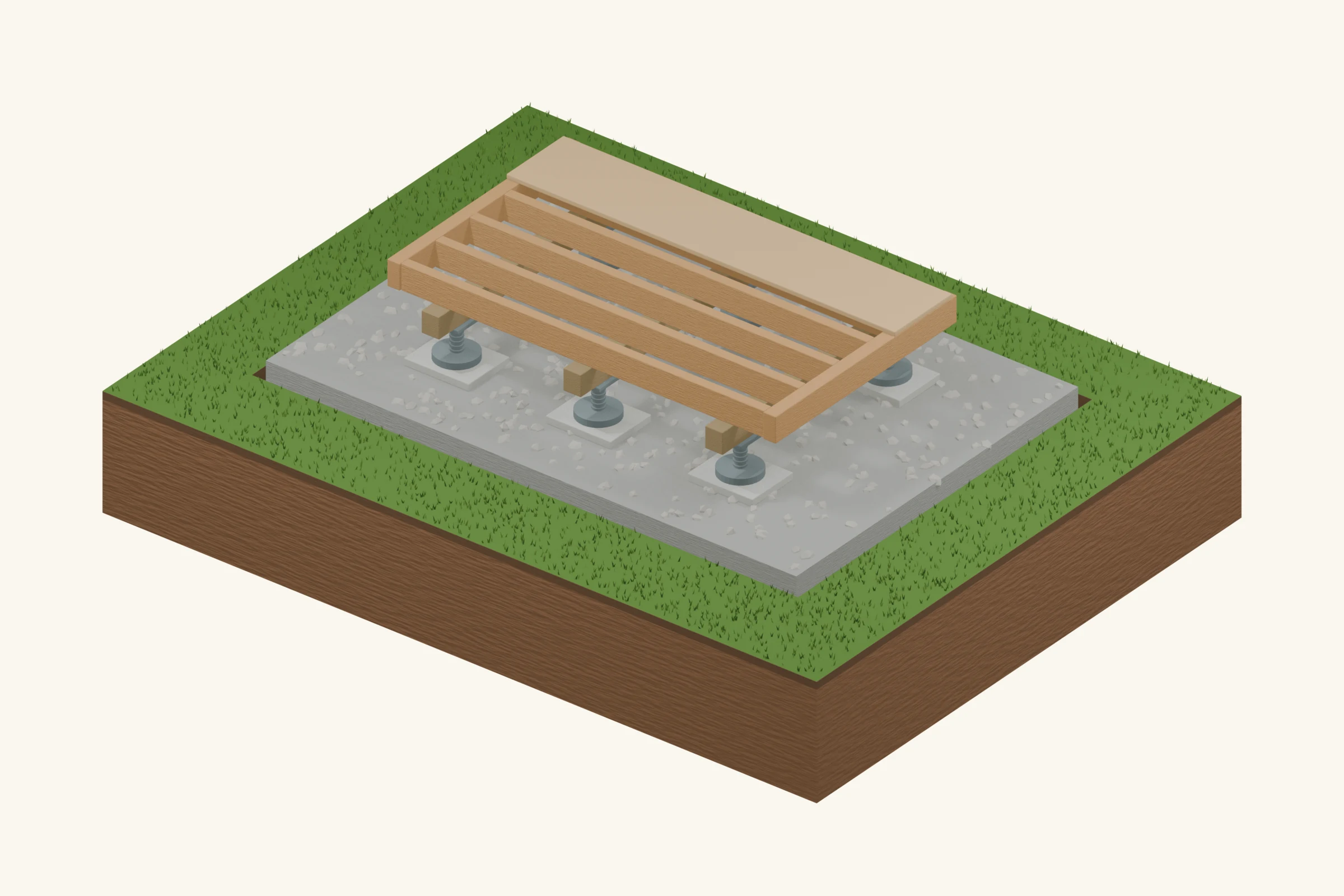
Metal bases include several fundamentally different products: surface screw jacks, adjustable post bases and installed ground screws. This article and its drawings cover surface-mounted leveling supports. Ground screws need their own geotechnical, installation and capacity design; a steel screw thread above a pad does not turn a surface base into a deep foundation.
Is it right for your shed?
Best fit: A compatible timber frame needing modest, controlled height adjustment on firm supports.
Advantages
- Threaded adjustment allows accurate final leveling.
- Rated steel heads can provide defined frame connections.
- Support details remain accessible for inspection.
Limitations
- Corrosion protection must match the exposure and treated timber.
- Slender extended stems need stability checks.
- A surface plate does not supply deep-soil anchorage.
What goes under it? The ground layers
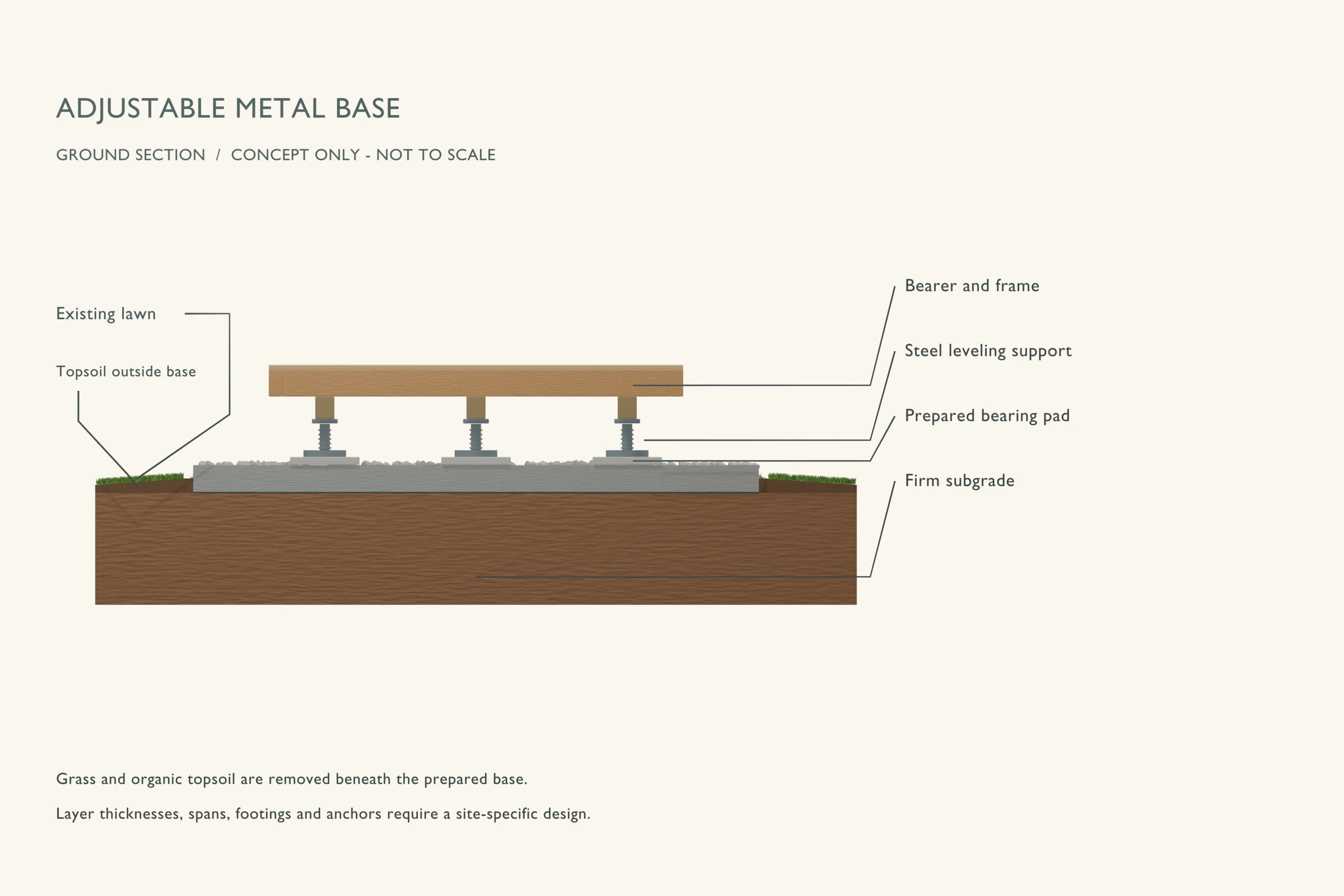
The explanation runs from the ground upward. Callout labels in the drawing identify the visible parts; some thin layers are enlarged for clarity.
- 1
Prepared soil
Verify bearing below the support pad.
- 2
Aggregate and bearing pad
Use a spreader surface sized for the support reaction.
- 3
Steel base plate
Provide full plate contact and the required fixings.
- 4
Threaded support and lock
Stay within the permitted adjustment range and lock the finished elevation.
- 5
Beam saddle and frame
Fasten the beam with the specified corrosion-compatible hardware.
Materials and preparation
Use the quantities and specifications from your actual layout. Before ordering, resolve the pad footprint, support locations, finished floor height and the drainage route.
- Rated leveling bases, locks and compatible fasteners
- Specified hard bearing pads and compacted base
- Designed floor frame, bracing and anchor system
Useful planning: choose the shed location and check permit requirements.
Build sequence
This sequence explains the order of work. Use it alongside the foundation design and the instructions for your chosen products.
Step 01
Identify the actual support category
Read the product documentation to establish whether it is a surface support or a ground-installed foundation. Confirm shed use and the load capacity at the intended height.
Step 02
Prepare pads and set out
Locate supports below the designed beam lines. Make each bearing surface level and stable; plate edges must not overhang a small paver or loose gravel heap.
Step 03
Install plates and heads
Fit only the specified anchors and fasteners. Maintain required edge distances in concrete pads and check that the connection can transfer the forces assigned to it.
Step 04
Level and lock the frame
Adjust within the stated limits, then secure lock nuts or the product locking device. Check the whole floor for twist, not merely one beam for level.
Step 05
Finish bracing and corrosion details
Add the planned lateral restraint and wind anchors. Avoid incompatible metals and repair coating damage using the manufacturer method.
Mistakes to avoid
- Calling a surface jack a ground-screw foundation.
- Using maximum thread extension without checking capacity.
- Treating a bolted saddle as proof of a complete wind load path.
Inspection and maintenance
Inspect coating, fasteners, locks and plate contact. Check for rust at cut edges and water traps. If supports need adjustment, use the documented safe unloading procedure before altering them.
When to choose a different base
A rated metal leveling system can suit a carefully detailed floor. If frost protection or a steep slope is the main problem, compare deep piers or an independently engineered ground-screw design.
Common questions
Are ground screws covered by this guide?
No. The drawings show surface leveling supports. Ground screws need product-specific installation verification and site capacity assessment.
Can a jack support a tall post?
Only within a system designed for that geometry, including lateral loads and bracing. Vertical load capacity alone does not establish stability.
Technical references
Use the currently adopted local requirements and the exact product instructions for your build. These references explain the principles behind this guide.
- ICC: 2024 IRC, Chapter 4 — Foundations
Model-code background for bearing and frost protection. Your adopted code and local amendments control.
- AWPA: treated wood guidance for homeowners
Use-category labels distinguish above-ground, ground-contact and more demanding exposures.