
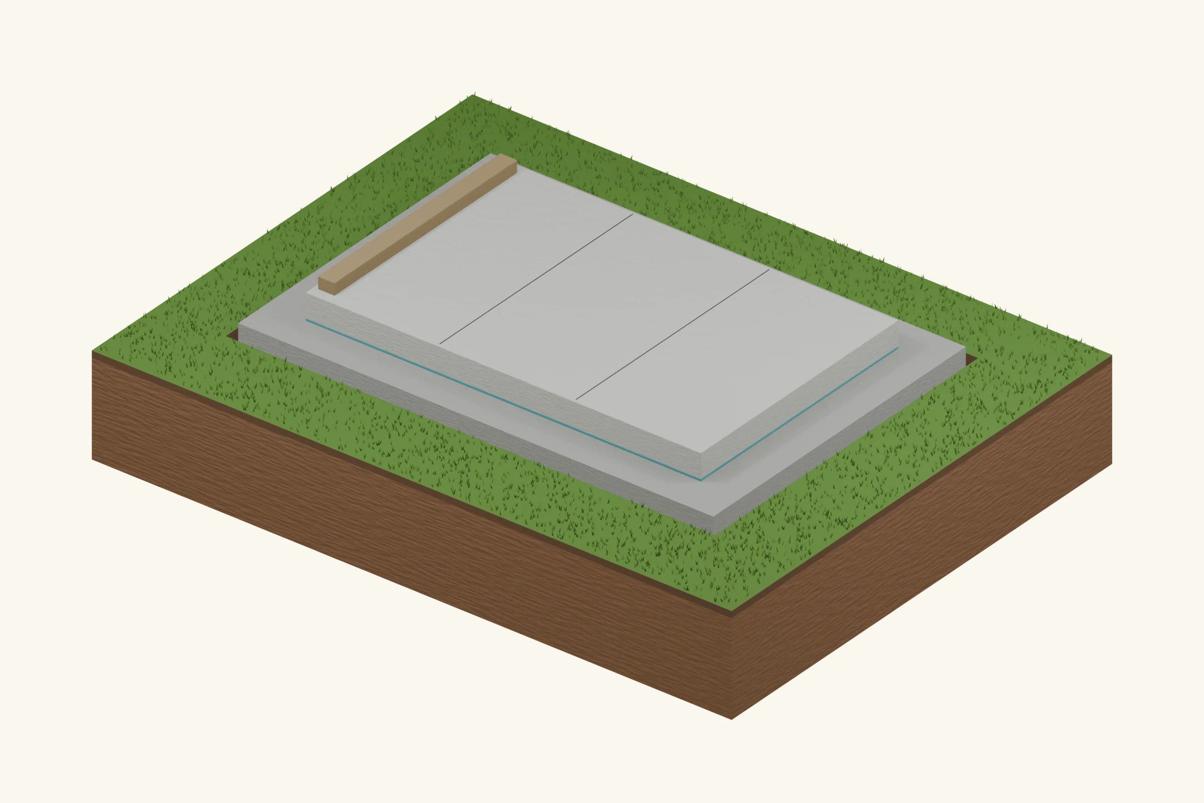
Concrete combines the appeal of a firm floor with the difficulty of changing it later. Begin with the intended use: garden tools, a workshop and a vehicle create different demands. The floor slab, wall support, anchors and frost protection may be one coordinated assembly or separate elements. The section shown here is a slab-on-grade concept, not an automatically frost-protected thickened-edge foundation.
Is it right for your shed?
Best fit: A workshop or storage building needing a clean solid floor, with a slab designed for its loads.
Advantages
- A continuous floor is convenient for rolling equipment and cleaning.
- Wall anchors can be coordinated before placement.
- Suitable design can address substantial concentrated loads.
Limitations
- Access, weather and the concrete delivery affect the pour.
- Drainage, utilities and anchors are hard to change later.
- A slab can crack and needs planned joints and curing.
What goes under it? The ground layers
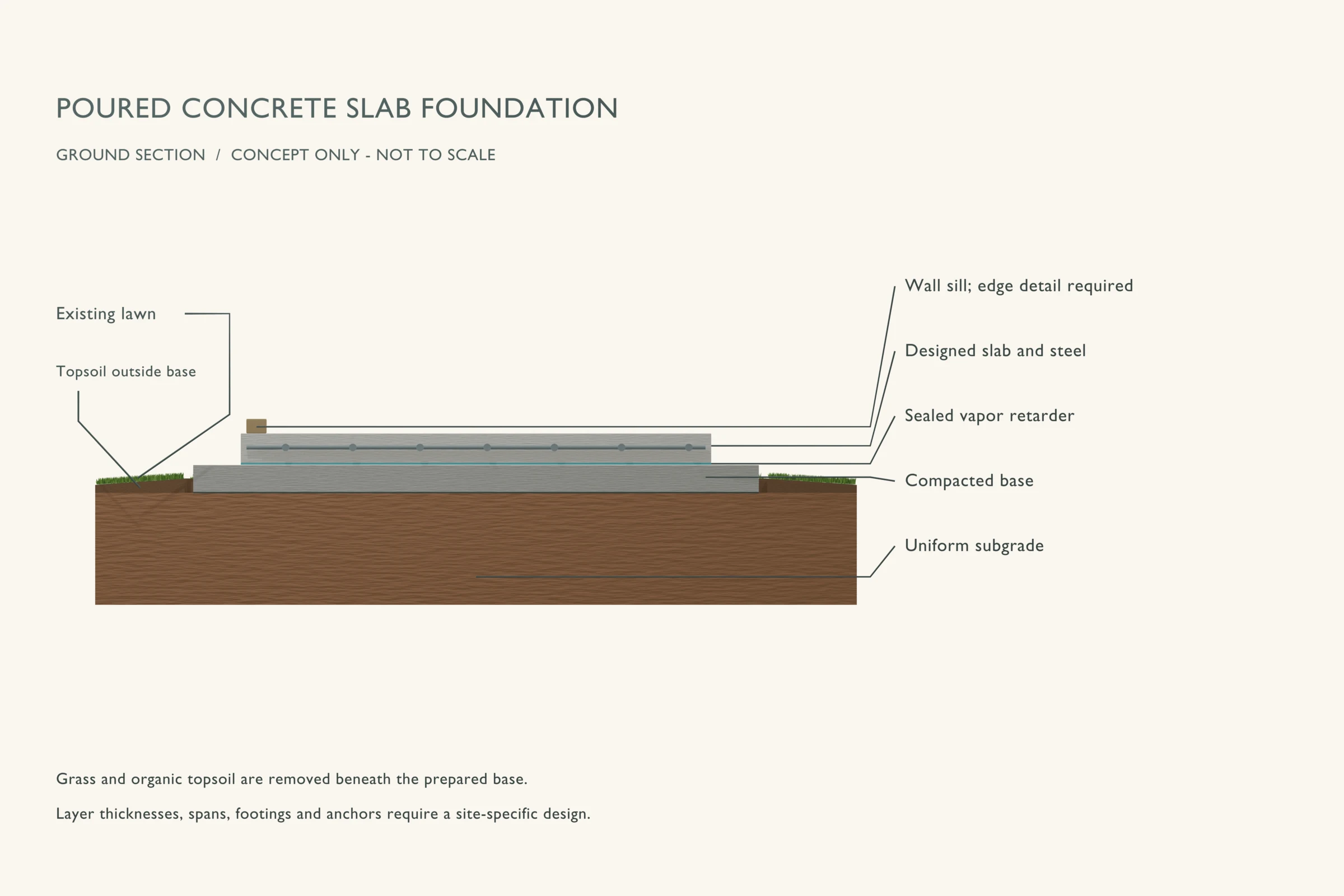
The explanation runs from the ground upward. Callout labels in the drawing identify the visible parts; some thin layers are enlarged for clarity.
- 1
Prepared subgrade
Uniform, accepted bearing supports the entire floor assembly.
- 2
Compacted granular base
The specified base creates a stable formation; drainage must lead somewhere.
- 3
Vapor retarder
Seal laps and penetrations where required by the moisture design; this is distinct from permeable geotextile.
- 4
Reinforced slab
Thickness, reinforcing location and joints follow the slab design, including concentrated loads.
- 5
Wall-bearing and anchors
The perimeter foundation and anchorage need explicit detailing; no frost-protection detail is implied by this drawing.
Materials and preparation
Use the quantities and specifications from your actual layout. Before ordering, resolve the pad footprint, support locations, finished floor height and the drainage route.
- Slab/edge design, specified concrete and reinforcement
- Compacted base, vapor retarder and any specified insulation
- Forms, chairs, anchors, placement/finishing and curing equipment
Useful planning: choose the shed location and check permit requirements.
Build sequence
This sequence explains the order of work. Use it alongside the foundation design and the instructions for your chosen products.
Step 01
Resolve the finished levels
Plan door threshold, exterior grade, floor finish and drainage before setting forms. Place service sleeves now and check that the foundation design suits the building and local frost requirements.
Step 02
Prepare and inspect the base
Remove organics, correct weak areas and compact the specified fill. Do not pour over frozen, muddy or pumping ground. Confirm the perimeter support detail and any pre-pour inspection requirements.
Step 03
Set forms and below-slab layers
Brace forms, install the specified moisture and insulation layers, and seal penetrations. A heated-house insulation detail cannot simply be copied for an unheated shed.
Step 04
Position reinforcement and anchors
Support steel at the designed elevation using suitable chairs. Tie and template anchors to the approved layout. Reinforcement lying on the ground is not at the designed position.
Step 05
Place, finish, joint and cure
Use a placement crew and concrete specification suited to the job. Execute the joint plan and begin the specified curing method promptly. Avoid adding water or premature finishing merely to speed the work.
Step 06
Wait for the loading release
Protect edges and anchors while the concrete gains strength. The surface looking dry is not a loading test. Confirm the required strength and moisture conditions before erection, heavy storage or moisture-sensitive flooring.
Mistakes to avoid
- Calling every monolithic slab frost-protected.
- Omitting the anchor and joint layouts until concrete arrives.
- Assuming a generic thin slab can carry a car or machine.
Inspection and maintenance
Keep joints and perimeter drainage serviceable. Monitor cracks for changes in width or level; a step across a crack deserves investigation. Follow coating and flooring instructions for moisture testing and preparation.
When to choose a different base
Choose a slab for the floor benefits and design it around actual loads. For a simple raised timber shed, a slab may add expense without replacing the need to coordinate the floor and wall details.
Common questions
Does a thickened edge stop frost heave?
Not on its own. Frost protection must follow the adopted requirements or an accepted engineered design; unheated buildings require specific attention.
Can I use a standard slab thickness for any shed?
No. Thickness and reinforcement depend on loads, soil support, joints and foundation arrangement. Vehicle and machine loads need explicit consideration.
Technical references
Use the currently adopted local requirements and the exact product instructions for your build. These references explain the principles behind this guide.
- NRMCA: Concrete in Practice
Concrete placement, joints and curing; see CIP 6 and CIP 11.
- NRMCA CIP 29: Vapor Retarders Under Slabs on Grade
Under-slab moisture control and vapor-retarder detailing.
- ICC: 2024 IRC, Chapter 4 — Foundations
Model-code background for bearing and frost protection. Your adopted code and local amendments control.
- HUD: Frost-Protected Shallow Foundations Design Guide
Heated and unheated buildings need different frost-protection designs.