
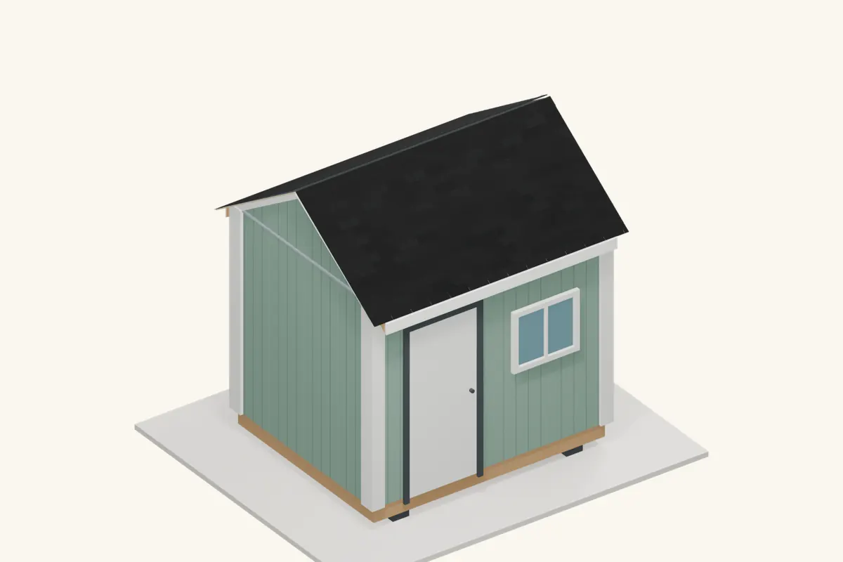
A gable roof has two slopes meeting at a ridge. Build one accurate rafter template, test it on the walls, then repeat the fitted shape. This sequence is for a timber shed with paired rafters and a designed arrangement of ties; a structural ridge beam or manufactured truss roof follows a different connection design.
- A good fit for
- A familiar pitched roof with space above the walls and two clear drainage edges.
- Plan for
- A framing plan that specifies the loads, timber grade, rafter spacing, ties and all connections before you cut.
Jump to a step
- 1.Set the pitch and roof assembly
- 2.Check the walls and mark the rafter positions
- 3.Lay out one rafter template
- 4.Cut the seat without overcutting the corner
- 5.Test-fit the first pair on the shed
- 6.Set the ridge and the designed ties
- 7.Erect and temporarily brace the end frames
- 8.Install the remaining rafters
- 9.Complete the roof-to-wall connections
- 10.Fit blocking and overhang supports
- 11.Lay and fasten the roof decking
- 12.Inspect before covering the frame
Materials and tools
Materials
- Graded rafters, ridge board, ties and blocking specified by your shed plan
- Wall plates, overhang framing and fascia backing
- Roof-rated plywood or OSB with the required span rating and edge support
- Specified framing nails, structural connectors and connector fasteners
- Temporary bracing and weather protection
Tools and access
- Tape, framing square, level, chalk line and straightedge
- Saw, clamps, drill and suitable nailer or hammer
- Stable work platform, lifting help and fall protection suitable for the site
Measure the actual roof and allow for laps, edge turns and cuts. Work from stable access with suitable fall protection; wet roofs and loose sheets are unsafe work surfaces.
Understand the roof assembly
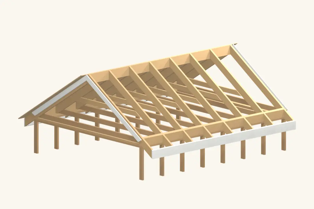
The framing views use the established SHED75 roof geometry as a visual reference. Low ties illustrate a conventional tied-rafter arrangement; the drawings are placement guides, not a structural design or a cut list for another shed.
Step 1 of 12
Set the pitch and roof assembly
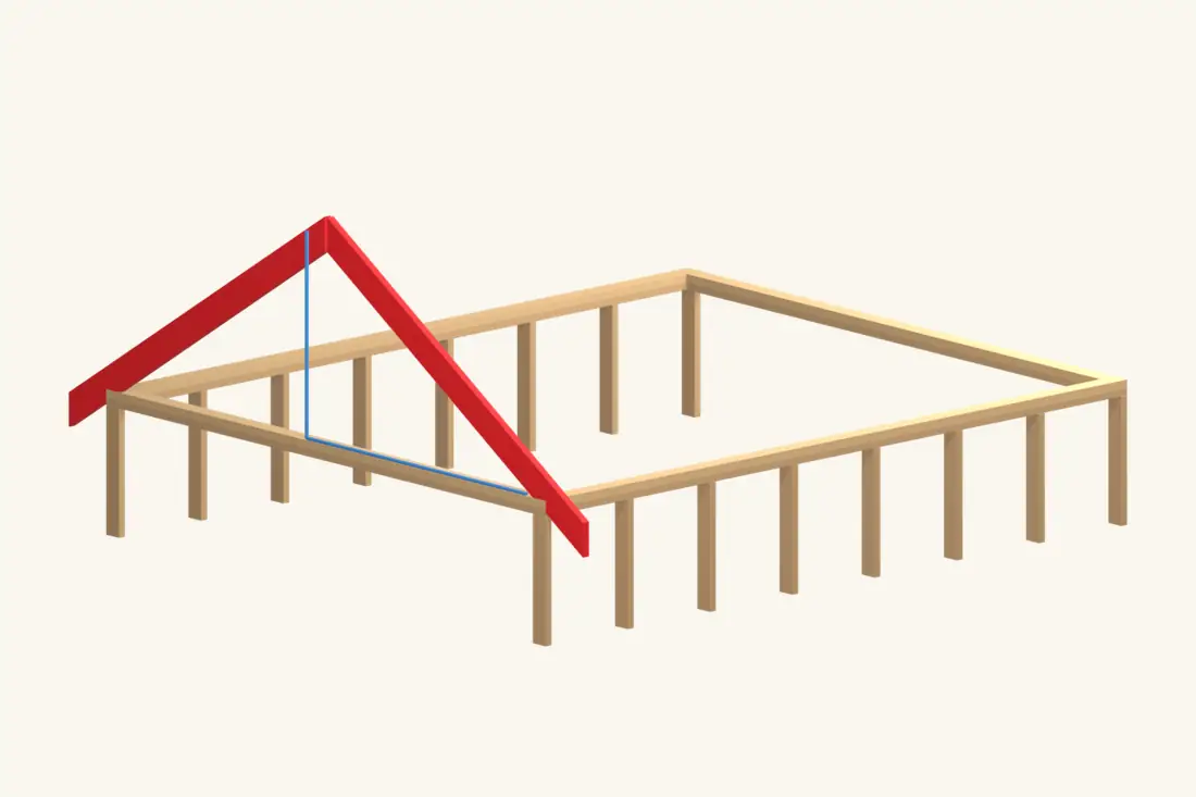
Choose the final roof covering before setting the ridge height. Write the shed span, roof pitch, overhang and bearing positions on your working drawing. Pitch is rise divided by horizontal run; 4:12 means a 4-inch rise for every 12 horizontal inches, not a 4-inch rafter length.
Have the timber sizes, spacing, ties and connections specified for your span and local snow and wind loads. A taller ridge or heavier covering changes the framing problem. Keep the cut list beside the drawing so quantities and lengths stay together.
Check before continuing: The framing plan and the covering instructions agree on the roof slope.
Installation reference: American Wood Council — span tables and design values
Step 2 of 12
Check the walls and mark the rafter positions
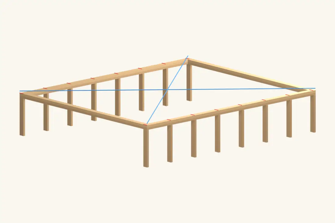
Measure the wall diagonals, check that the plates are straight and confirm that the walls are plumb and braced. Correct the walls now: identical rafters will not fit a twisted rectangle consistently.
Mark the paired rafter positions on both bearing plates and the ridge, using the plan spacing from a single starting end. Mark the side of each line where the timber belongs. Carry the same layout through to ties, blocking and supported deck joints.
Check before continuing: Opposite rafter marks align; the walls stay braced during roof erection.
Step 3 of 12
Lay out one rafter template
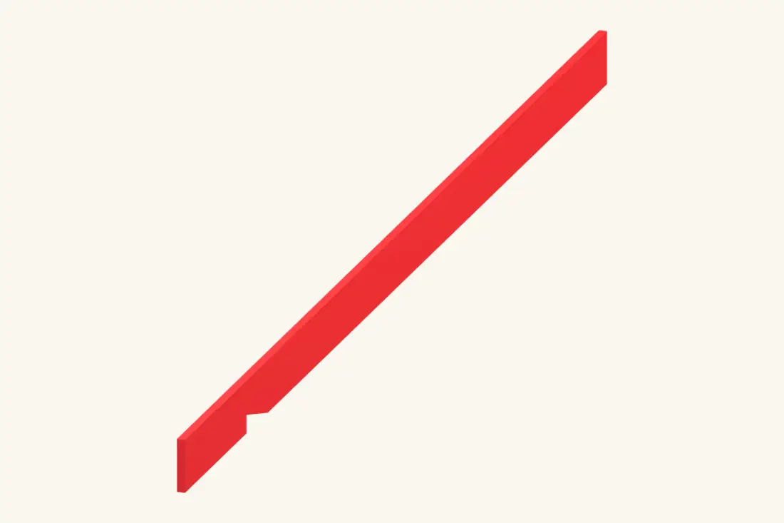
Select a straight board and mark its crown. Lay out the ridge plumb cut with a framing square or a verified angle setting. Measure the run to the outside bearing line and account for the ridge thickness using the plan detail.
Mark the seat, heel and overhang tail on this same board. Label the ridge end and wall-bearing line before cutting. A template should represent the finished geometry, not accumulate measurements from a previously shortened offcut.
Check before continuing: Ridge, bearing and tail marks all come from the same roof layout.
Step 4 of 12
Cut the seat without overcutting the corner

The birdsmouth has a level seat that bears on the wall plate and a heel cut meeting it. Set the saw to the marked lines, stop short of their intersection and finish the corner with a hand saw. Do not run the circular blade beyond the corner into the retained timber.
Use the notch depth and bearing length allowed by the framing design. Keep the remaining rafter section intact. If the template does not seat properly, correct its layout rather than enlarging the notch repeatedly.
Check before continuing: The seat bears flat and the notch stays within the specified limits.
Installation reference: American Wood Council — span tables and design values
Step 5 of 12
Test-fit the first pair on the shed
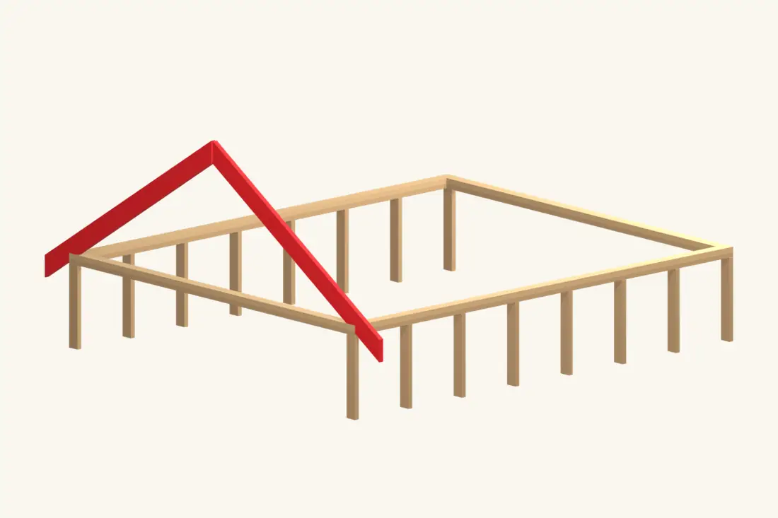
With lifting help and temporary supports, offer up a left and right rafter at the same station. Check the ridge junction, both wall seats and both tails. The ridge position should follow the drawing without pushing either wall outward.
Clamp or temporarily secure the trial pair as needed while checking. Transfer only the proven template to the remaining boards; keep their crowns consistent. Mark each rafter before moving it to the stack.
Check before continuing: Both seats bear evenly and the ridge ends meet the specified ridge detail.
Step 6 of 12
Set the ridge and the designed ties
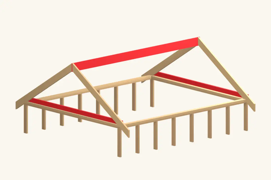
Support the ridge at its specified height and position. Fit the tie arrangement that keeps the rafter feet from spreading the walls. In a conventional tied roof, low rafter ties and high collar ties do different jobs; a collar tie is not a substitute for the required low tie.
Use the specified fasteners and connection lengths. An open ceiling may require a designed structural ridge beam and posts instead of low ties. Do not remove ties later to create headroom without redesigning that load path.
Check before continuing: Rafter thrust has the tie or structural support required by the design.
Installation reference: American Wood Council — span tables and design values
Step 7 of 12
Erect and temporarily brace the end frames
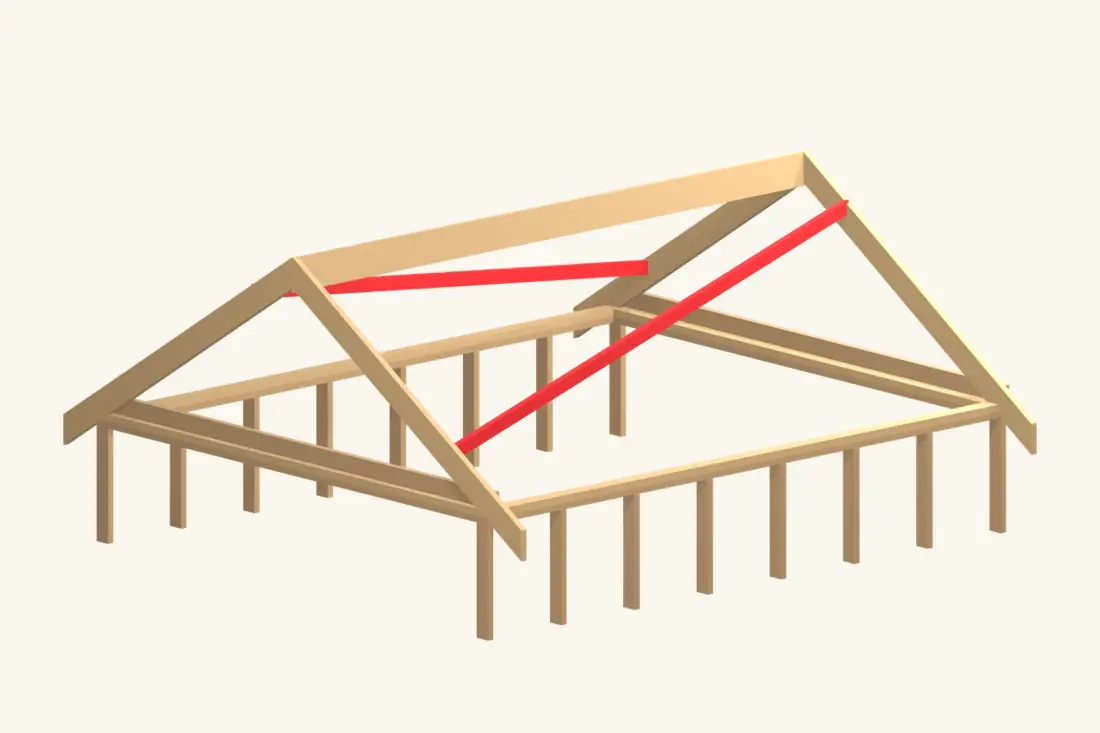
Position the end rafter pairs, secure their designed connections and brace them against movement along the shed. Check plumb from a stable platform. Temporary braces need firm fixing points; a loosely leaning board does not hold a frame in position.
Run an alignment line between the ends to guide the intermediate rafters. Keep braces in place until the permanent bracing and decking provide the restraint specified by the plan.
Check before continuing: End frames are stable, plumb and aligned before more timber is lifted.
Step 8 of 12
Install the remaining rafters
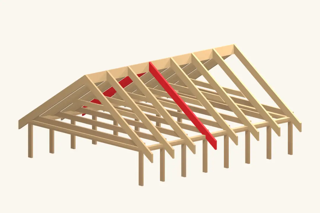
Work from the same layout end, placing each rafter on its marked side of the line. Fit the matching opposite member and required tie at that station. Check the roof plane with a straightedge or line as the frame grows.
Do not force a bowed board into place with a roof sheet. Replace or correct unsuitable members before decking. Keep the roof evenly loaded while carrying and lifting materials.
Check before continuing: Rafters follow the layout, seats remain supported and the roof planes are straight.
Step 9 of 12
Complete the roof-to-wall connections
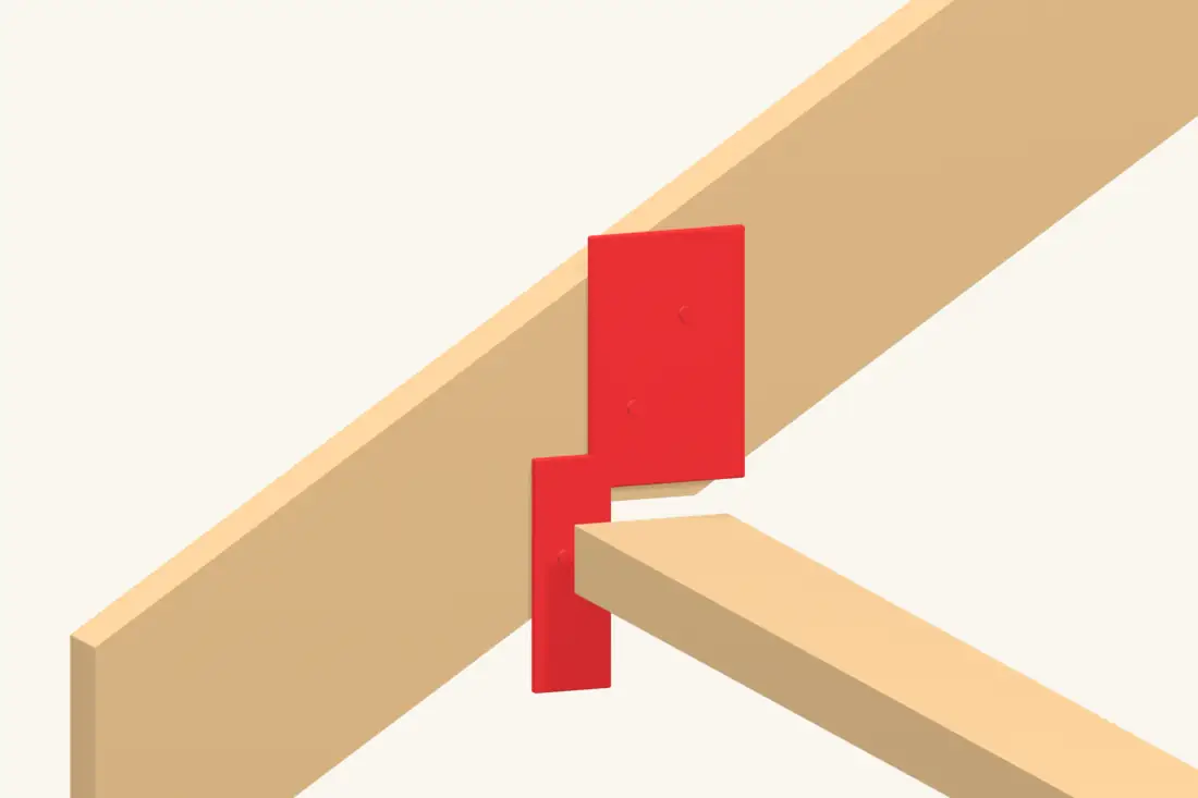
Install the straps, clips or other connections called for by the plan at every required position. Seat each connector against the timber and drive the specified fasteners into the specified holes.
Connector nails and structural screws have defined jobs. Ordinary deck screws are not automatic substitutes. Check both sides of the shed and the connection into the wall below, not only the metal clip visible at the rafter.
Check before continuing: Every required connector is complete and uses its listed fasteners.
Installation reference: Simpson Strong-Tie — wood connectors and specified fasteners
Step 10 of 12
Fit blocking and overhang supports
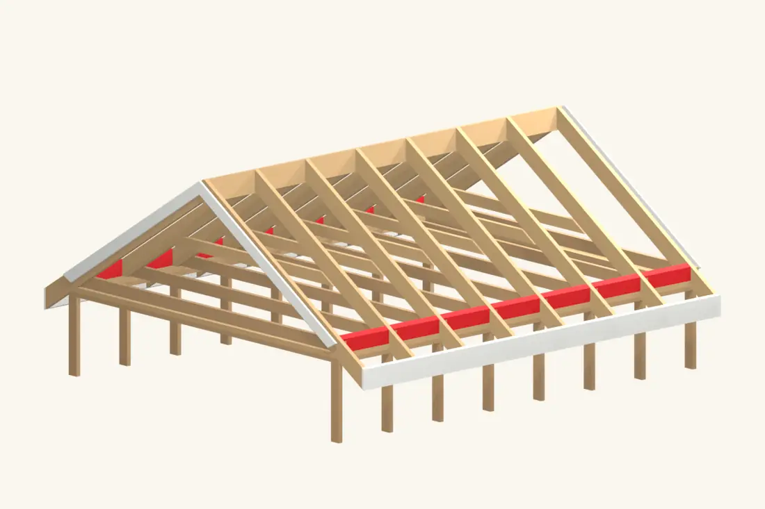
Cut and fit the rafter-bay blocking shown on the plan. Add the designed eave and rake support before attaching fascia or verge boards. Each edge member needs a clear connection back to the structure.
If the roof assembly needs eave ventilation, preserve its planned air route when fitting blocking and trim. Use a straightedge to set the fascia line so the roof covering will finish at an even edge.
Check before continuing: Blocking and edge members are supported; intended ventilation paths remain open.
Step 11 of 12
Lay and fasten the roof decking
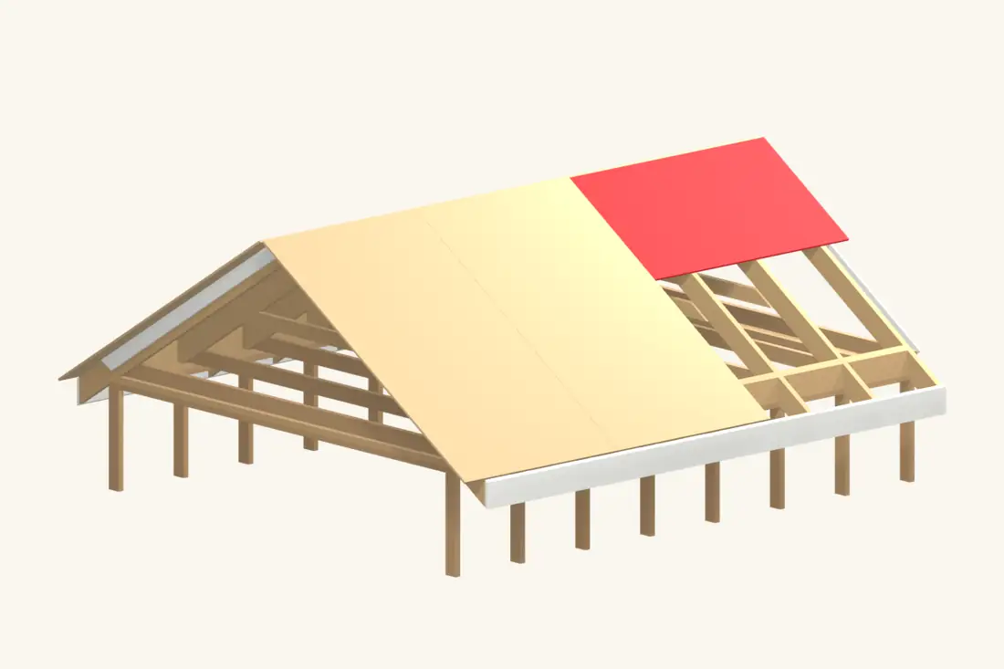
Start from a straight edge and place the panels with their strength axis across the rafters. Stagger supported end joints between rows. Fit the blocking or panel-edge clips required by the deck span and panel specification.
Leave the panel spacing recommended by the panel maker; APA commonly recommends 1/8 inch at edges and ends unless the manufacturer states otherwise. Fasten to the specified schedule with heads flush, and keep checking that the panel edges land on support.
Check before continuing: Panel joints, edge support and fastener lines match the deck specification.
Installation reference: APA — roof sheathing and roof systems
Step 12 of 12
Inspect before covering the frame
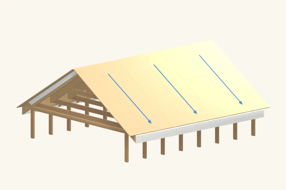
Check the ridge, both roof planes, bearing seats, ties, connections and roof edges. Remove protruding fixings and repair damaged or unsupported deck areas. Record any framing inspection required before covering the work.
Protect the deck from weather and move on to the roof covering while the substrate is sound and dry. Use the separate shingle or metal guide for its eave, underlay and ridge sequence; the covering does not replace missing structural connections.
Check before continuing: The roof is stable, fully connected and ready for its specified weatherproof covering.
Installation reference: APA — roof sheathing and roof systems
Common questions
Can I use 2×4 rafters for any small shed?
No. Select rafters by clear span, spacing, timber species and grade, roof dead load and local snow and wind requirements. A small footprint alone does not establish a safe member size.
Are collar ties the same as rafter ties?
No. Low rafter ties resist the outward thrust of a conventional tied-rafter roof. Collar ties near the ridge serve a different connection role. Follow the designed position and fastening of each.
Can I make plywood-gusset trusses from a video?
Use a designed truss detail for your span and loads, including timber, gusset material, grain direction and fastening. A video assembly is not proof that the same joint works on a different shed.
Installation references
Checked 24 October 2026. Use the current instructions for your product and region, together with your shed’s framing design.