
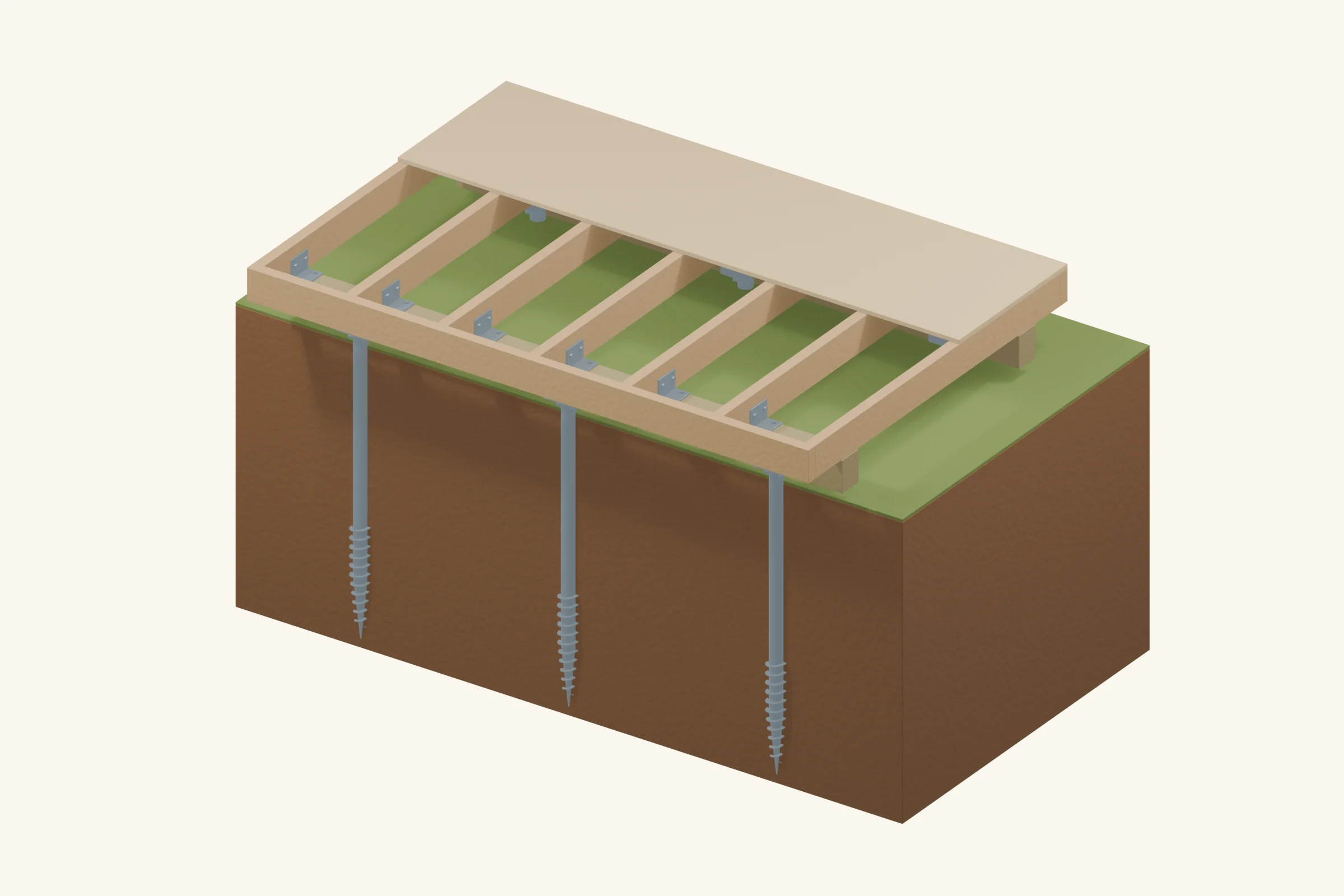
Ground screws turn into the soil and carry the shed through a raised timber floor. U-shaped heads hold the supporting beams above the ground. This guide follows a screw with an insertable U-head, a system sold in the US by American Ground Screw. The Lithuanian U-type screws use the same basic beam-support idea, with a different head detail.
Is it right for your shed?
Best fit: A timber-floor shed where a supplier can specify and install load-bearing screws for the site.
Advantages
- No concrete curing delay.
- Keeps structural timber above the soil.
- Can reduce excavation and disturbance around the shed.
Limitations
- Soil, building loads and frost affect the required screws.
- Rock, buried debris or weak fill may need a different installation method.
- Tall exposed shafts need specific lateral support; they are not freely adjustable posts.
Ground layers
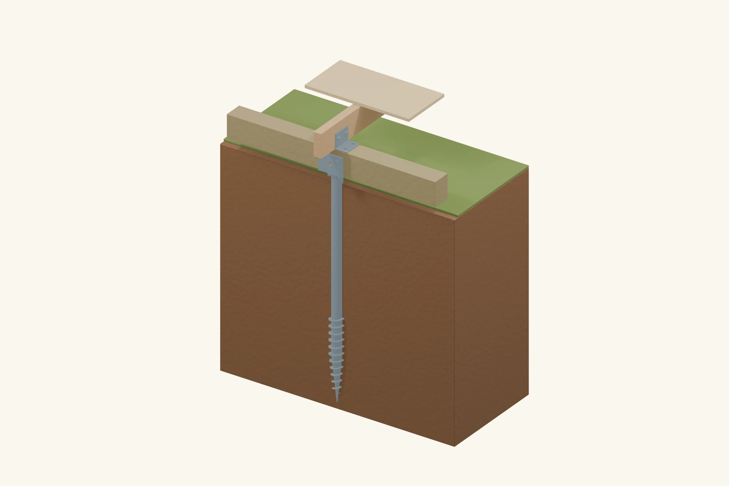
Read these layers from the ground up.
- 1
Soil carrying the load
The screw engages suitable soil below the surface. Capacity must be established for the actual site.
- 2
Embedded steel screw
The threaded lower section transfers loads into the soil. Length and frost protection come from the foundation design.
- 3
U-shaped beam head
The insert seats fully into the screw and is locked in place. Its saddle supports and secures the timber.
- 4
Supporting timber beams
Beams sit flat on the saddle seats, above soil and standing water.
- 5
Connected floor frame
Joists and a structural deck carry the shed onto the beams. The whole structure needs a continuous hold-down connection.
What you need
Get quantities and sizes from your shed plan.
- A foundation layout specifying screw model, length, positions, installation acceptance and head height
- Compatible galvanized U-heads, their locking bolts and specified timber fasteners
- Treated supporting beams sized for the floor and support spacing
- Floor joists, rim boards, structural deck and beam-to-floor connectors from the shed plan
- Layout lines, level and the manufacturer-approved installation equipment
Useful planning: choose the shed location and check permit requirements.
Build it step by step
Step 1: Plan and mark the supports
Start with the shed floor drawing and a supplier-designed screw layout. Confirm soil suitability, frost depth, building loads and any local approval before ordering. In the US, contact 811 before installation and arrange location of private buried services too. Square the footprint and mark each support. The illustrated six supports explain the arrangement; they are not a spacing schedule.
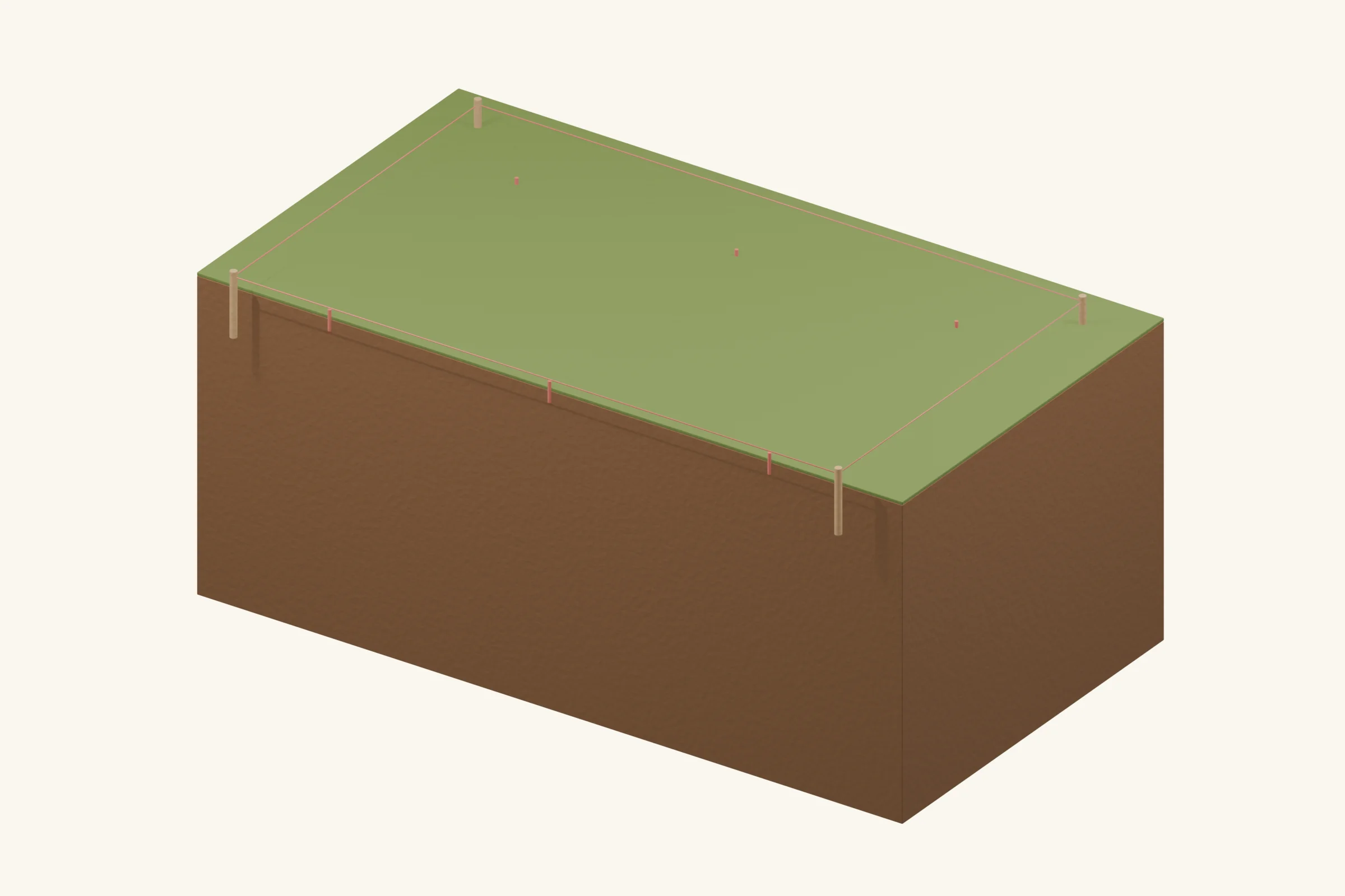
Mark the screw centres from the designed support layout. Six positions are shown only to explain this example; spacing and quantity depend on the shed. Step 2: Install the ground screws
Use the specified driver and follow its operating instructions. Keep each screw plumb as it advances. A powered driver needs its reaction arm secured as instructed, never held by hand. Have the installer verify the required embedment and capacity, including any specified torque records or tests. If a screw spins without advancing or meets an obstruction, resolve it with the supplier before continuing.
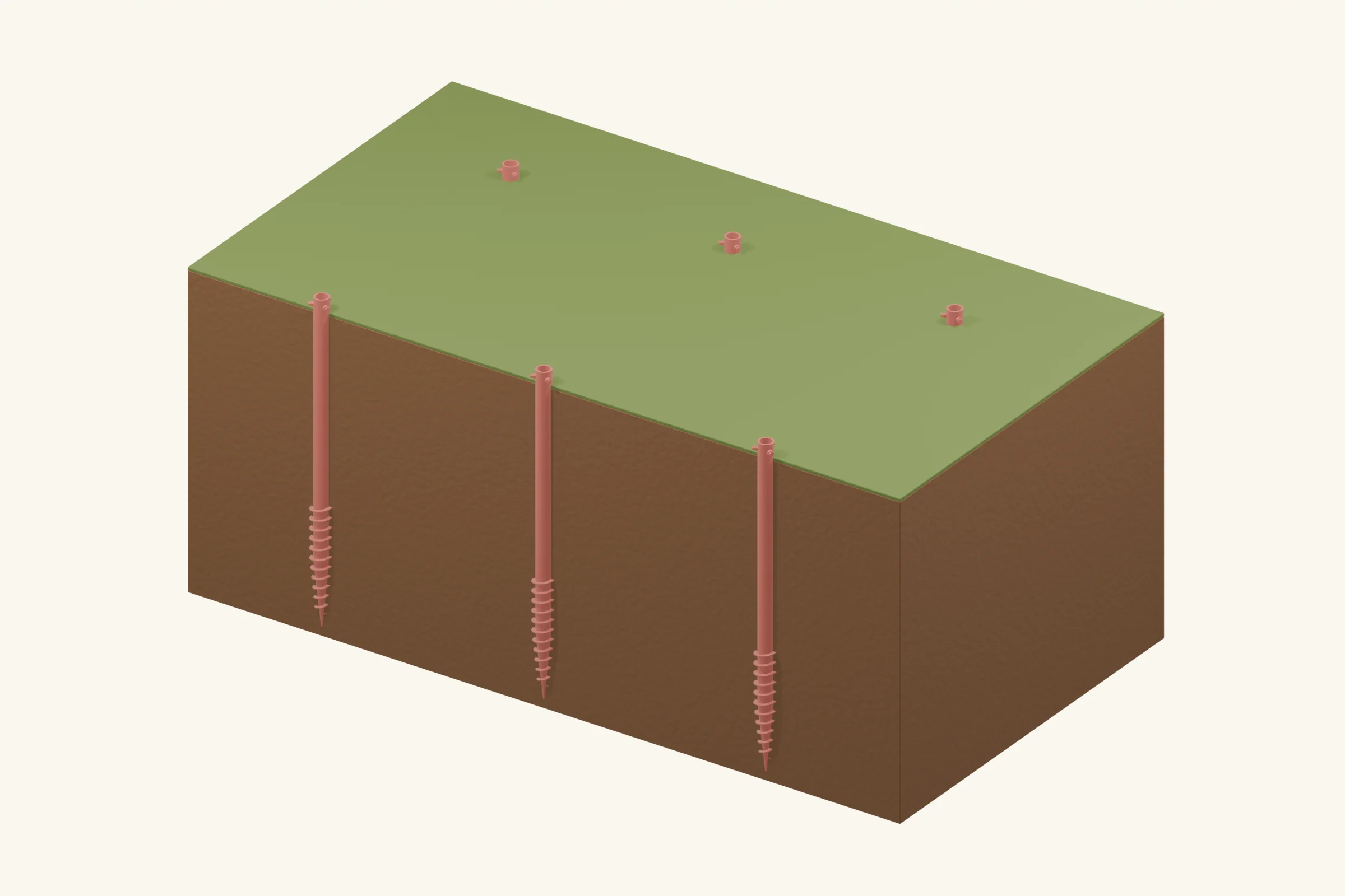
The front soil cutaway exposes the installed screws. Red identifies the steel added in this step. Depth and capacity must be verified for the site. Step 3: Seat and level the U-heads
Check the finished support elevations before fitting the beams. For the illustrated open-top system, insert each compatible U-head until its base sits flush on the screw top, align it with the beam, and tighten the three locking bolts as instructed. Do not lift the insert out to create extra height or back a screw out simply to level it. Use the system’s approved correction method.
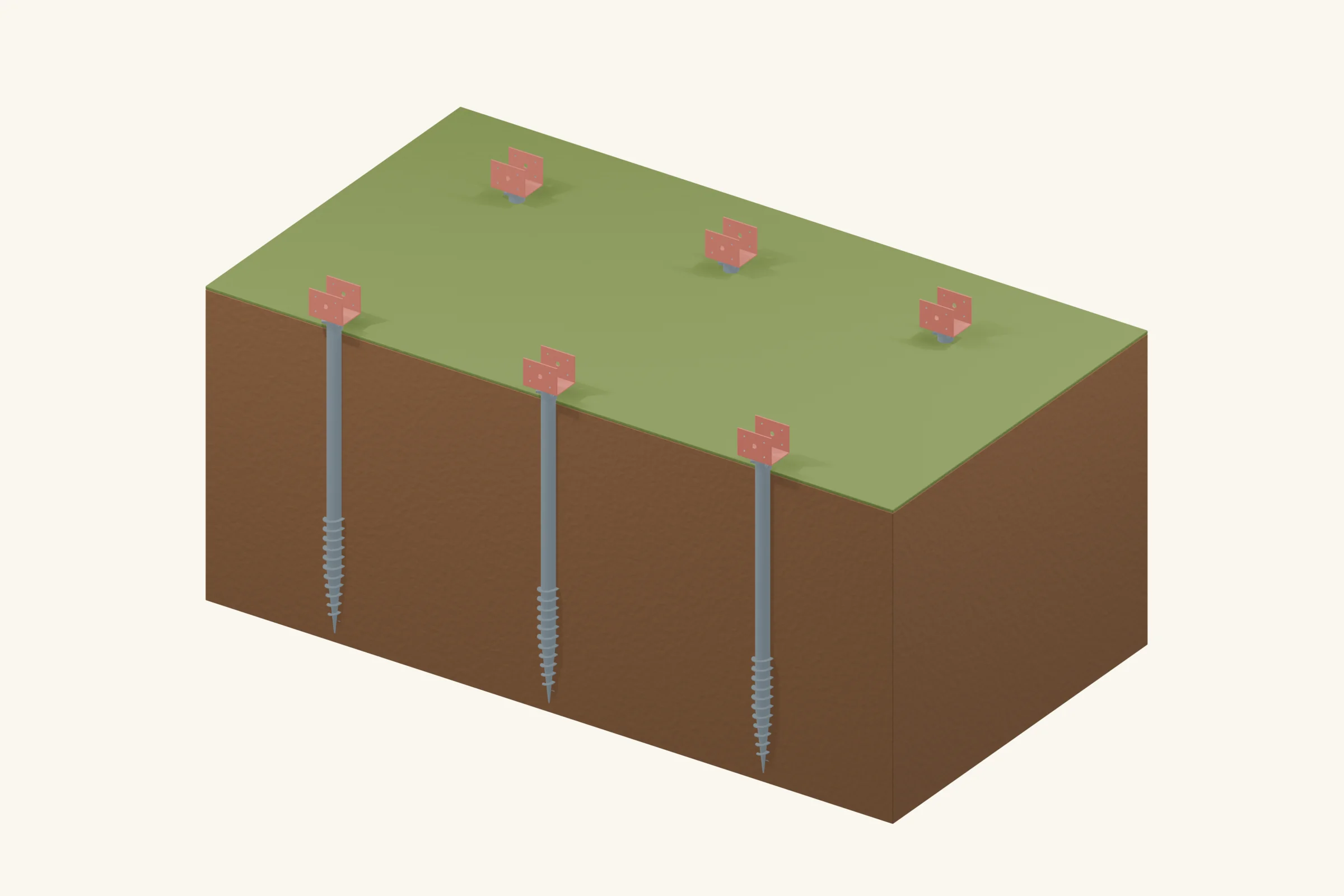
Fit the red U-heads fully onto the installed screws and lock their stems in place. Align the saddles to carry the beams at the planned height. Step 4: Secure the beams in the U-heads
Fit and fasten the supporting beams before the floor hides access. This example uses the U-head’s timber screw holes; the connection is part of the foundation, not an optional accessory.
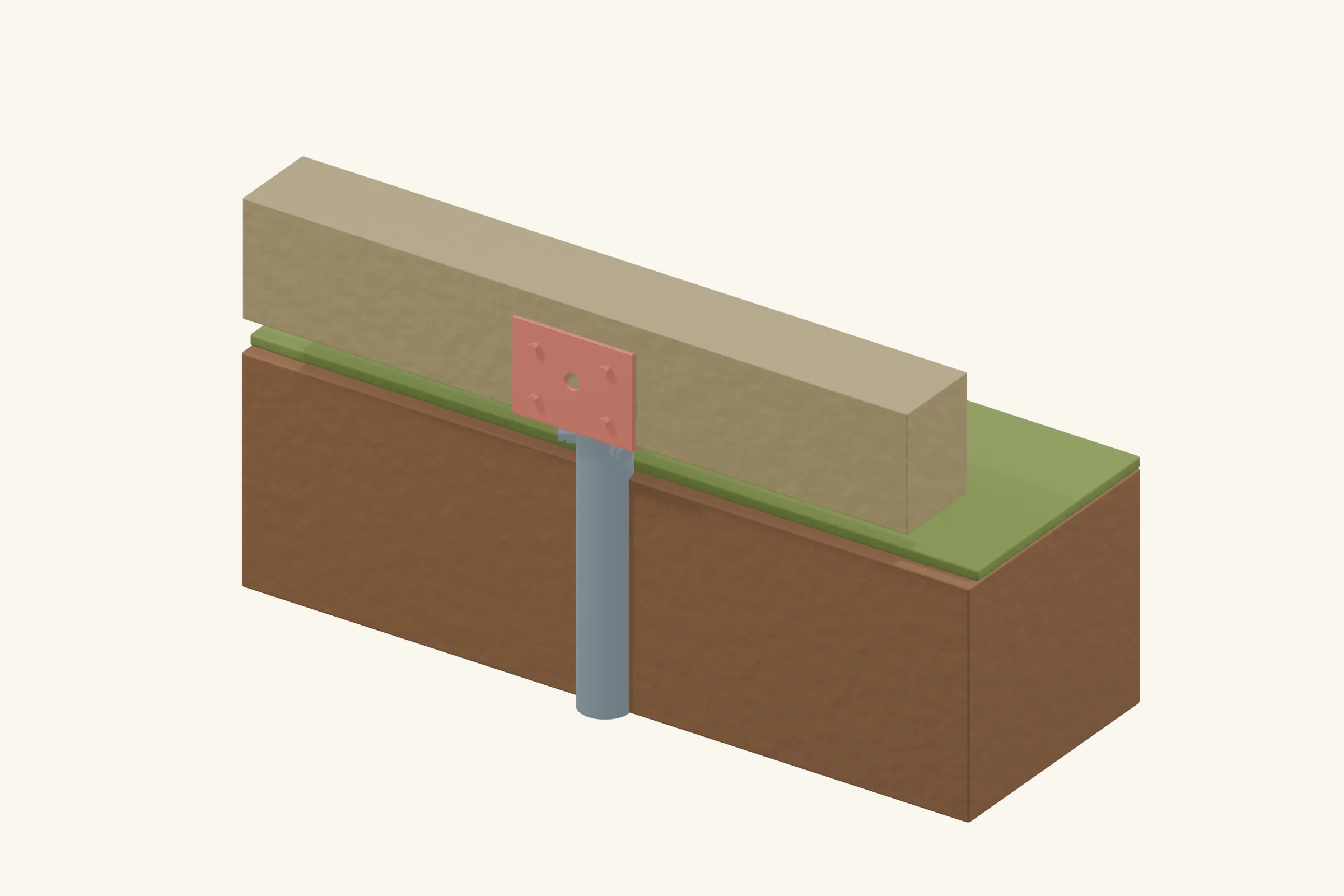
The timber bears on the red U-head seat. Structural timber screws secure both sides; three locking bolts secure the head stem inside the shaft. The shaft continues below this close-up. Use the selected head’s fastening schedule. - Use a head matched to the actual beam width. Rest the beam fully on the saddle’s bottom plate, with the head locked into the screw below. Do not hang the beam from side fasteners above the seat.
- Install the specified exterior structural timber screws through the designated holes on both sides, following their pilot-hole, penetration and edge-distance requirements. Use the head supplier’s fastening schedule; ordinary deck screws are not a substitute.
- Check the head locking bolts and every beam fixing before adding joists. A different head may specify through-bolts instead; follow that head’s detail rather than combining the two methods.
This fastening is required for the illustrated system. Screw depth, head height, fastener type and fixing pattern must match the foundation specification. The cutaway is an assembly example, not a dimensioned design.
Product example: American Ground Screw: structural screws and beam flanges.
Step 5: Build and connect the floor
Install the rim boards and joists on the secured beams, using the shed plan’s connectors and any specified bracing. Check square and level, then fasten the structural floor deck. Continue the hold-down connection through the walls and roof as the shed goes up. Keep drainage and underfloor ventilation clear.
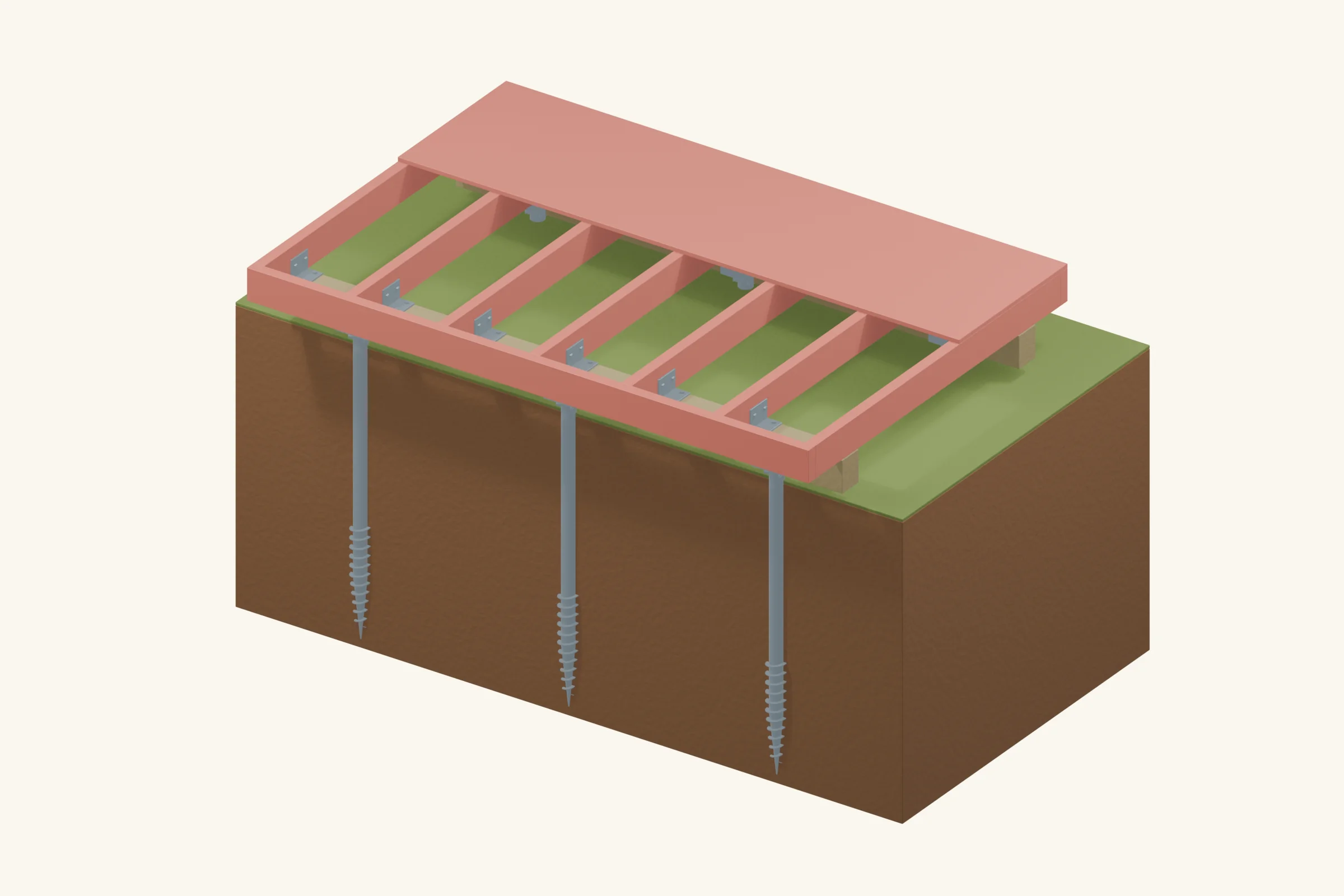
Add and connect the floor frame after securing the beams. Red shows the new joists, rim boards and partial deck; the cutaway leaves the foundation visible.
Mistakes to avoid
- Choosing short fence-post screws or 18-inch hold-down anchors as weight-bearing footings without a suitable structural specification.
- Treating a product’s advertised load as the capacity in every soil.
- Leaving excessive shaft exposed on a slope or using loose packing under beams.
- Resting timber in a U-head without fastening it, or omitting the floor-to-beam connection.
Keep it in good shape
Inspect accessible heads, locking bolts, timber fixings and drainage. Investigate leaning, settlement or corrosion with the installer. Do not adjust a loaded foundation by turning its screws.
When to choose a different base
Choose ground screws when a supplier can provide a foundation specification and suitable installation for your shed. Concrete piers remain an alternative where screw installation or verification is impractical.
Common questions
Are U-head ground screws available in the USA?
Yes. American Ground Screw offers open-top Model 3 screws with insertable beam flanges, including Models 44 and 66. These are US examples of the support arrangement shown here. Order the screw, head and fixings as a compatible system; a European product’s dimensions or load claim do not automatically apply.
Are these the same as the short anchors used beside skids?
No. Here the screws carry the building’s weight through the beams. The short screw-and-L-bracket anchors in our skid guide hold a separately supported shed down. They are not a substitute for these footings.
Do I need separate ground anchors?
A complete screw foundation can provide bearing, uplift and lateral resistance when all are included in its design. The U-head and beam fasteners are required parts of that connection. Separate hold-downs or bracing are needed if the design calls for them; do not add the short skid-anchor kit as an assumed cure for an unverified foundation.
Can I install them by hand?
Some small household screws allow manual installation. Structural systems commonly use powered installation equipment. Use the installation and acceptance method for the exact screw and shed; being able to turn a screw into the soil does not establish its load capacity.
What about welded U-head screws and helical piles?
A welded U-head removes the separate head-to-shaft joint, but still needs the right timber fastening and site-specific capacity. Installed helical piles are another steel footing system; their shafts, helices, brackets and installation criteria differ. Use one complete supplier specification rather than mixing parts.
Further reading
- American Ground Screw: structural screws and beam flanges
US system example: Model 3 screws with compatible insertable U-shaped beam heads.
- American Ground Screw: installation manual
Installation equipment, plumb alignment, head seating and locking bolts.
- American Ground Screw: design, soil and frost questions
Capacity and acceptance depend on the project, soil and selected system.
- Įsukami poliai: U-type ground screws (Lithuania)
European examples with welded U-shaped heads; specifications differ from the US system illustrated here.
- Techno Metal Post: shed and shelter foundations
Installed helical piles are a different foundation system from surface leveling feet.
- Simpson Strong-Tie: connector holes and fastener types
Use the connector's specified fastener type, size and installation pattern.
- American Wood Council: sill-plate anchorage and the continuous load path
Connect the structure all the way to its foundation; the weakest connection matters.