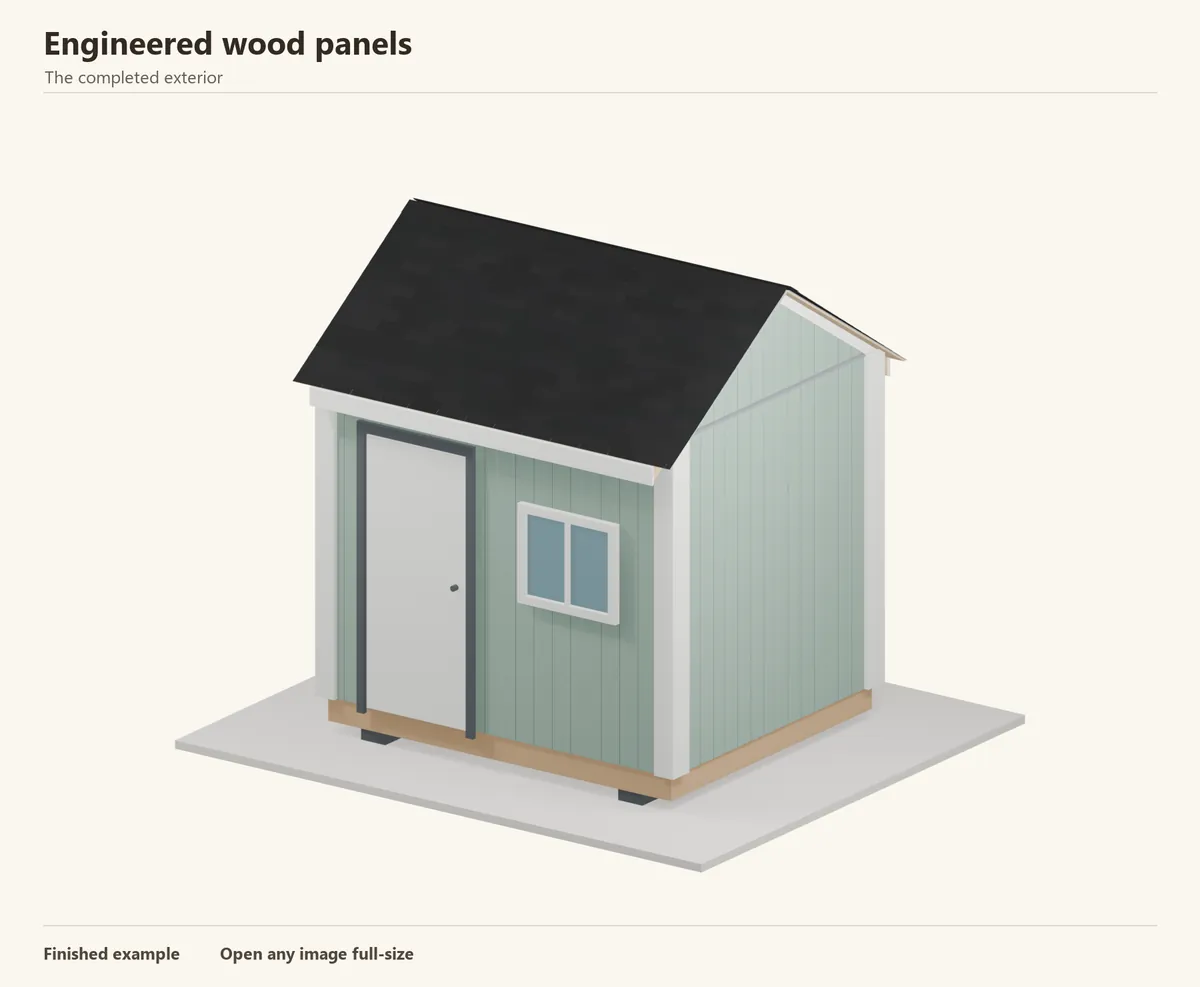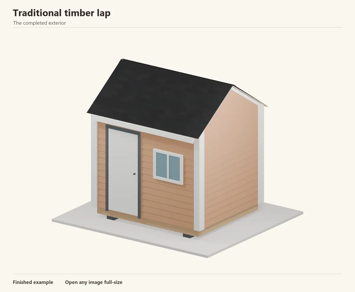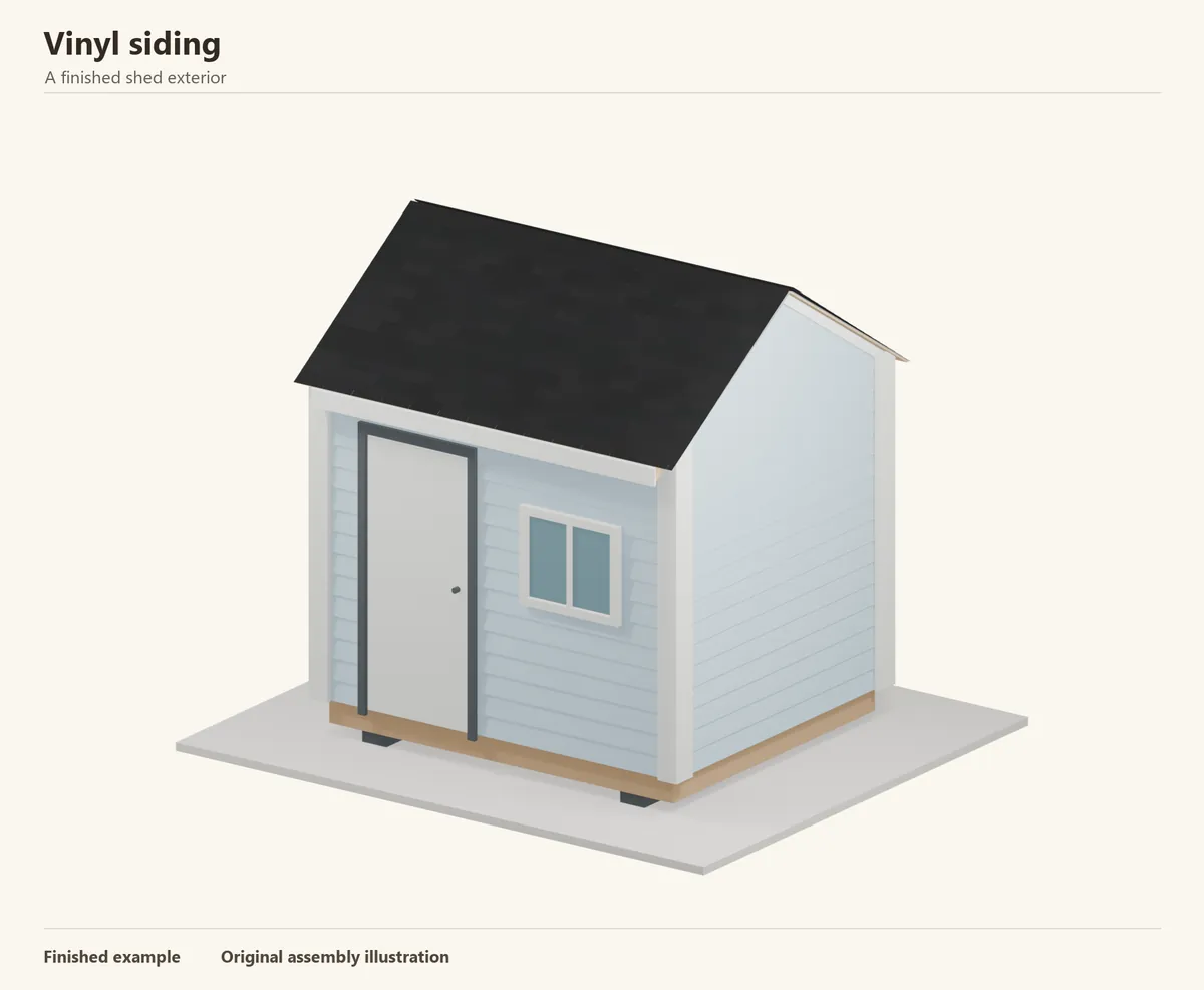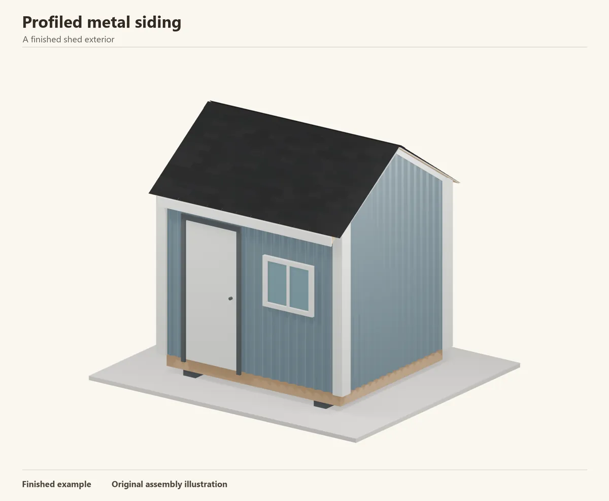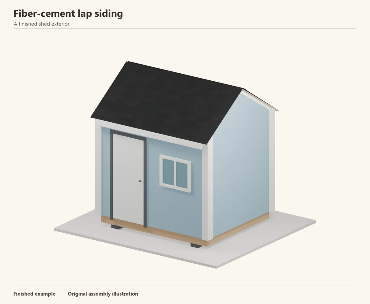
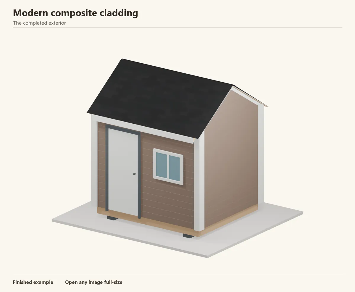
- A good fit for
- A contemporary shed with consistent horizontal lines and a factory-finished surface.
- Plan for
- Profiles vary. Buy boards, fasteners and trims that belong together, and allow for movement rather than treating composite like solid timber.
Jump to an installation step
- 1. Prepare and weatherproof the wall
- 2. Fit the vertical battens
- 3. Keep the base clear and drained
- 4. Set the first board level
- 5. Engage the next board
- 6. Predrill and screw through the flange
- 7. Continue with supported end joints
- 8. Cut around the flashed openings
- 9. Fit the corner covers
- 10. Cover the final fixing edge
- 11. Clean and inspect the wall
Before you begin
Buy the cladding and its required accessories together. Measure the wall area and openings, then calculate coverage using the actual product profile and allow for cuts.
- Exterior-rated flat WPC boards with an integral fixing flange
- Specified battens, structural batten fixings and cavity closures
- Sheathing, weather barrier, compatible tape and opening flashings
- Approved flange screws, matching trims and top-finish fasteners
- Tape, square, long level, straightedge, saw, drill and the specified drill bits
- Eye, hearing and dust protection; a stable working platform
Companies offering this type of siding include EnviroBuild, NewTechWood and Everlast. Check local availability and follow the installation instructions for the product you choose.
Choose the appearance and the fixing system together
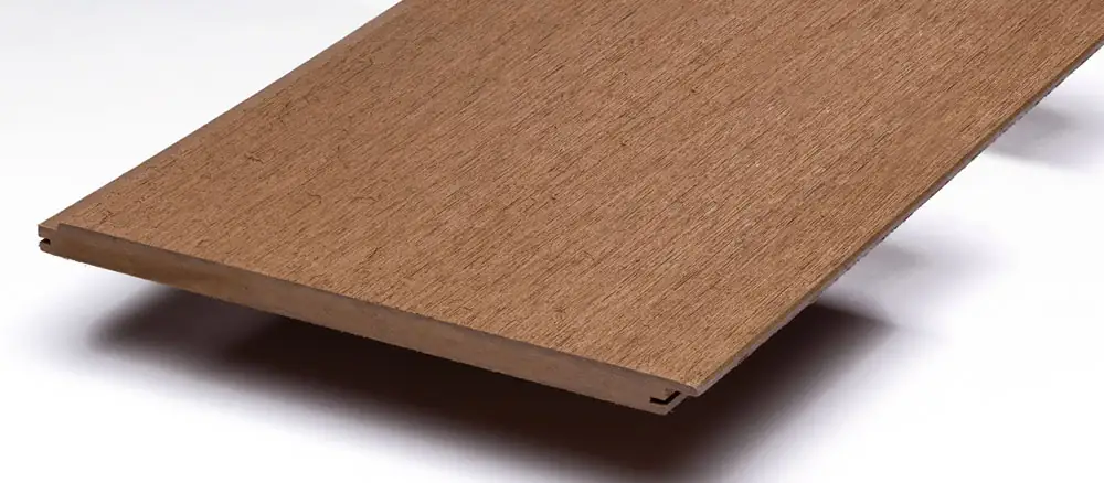
Wood-plastic composite can have a flat, textured or ribbed face. The sample photograph shows one material profile; the drawings below use flat horizontal boards. Check an actual offcut before ordering so you can see the face, the back and the interlocking edges.
Compare a complete wall package: boards, battens, corners, opening trims, screws and delivery. A small shed may use only a few board lengths, but it still has four corners and several terminations. Those accessories can change the apparent price advantage.
The simple method: fix through the board’s own flange
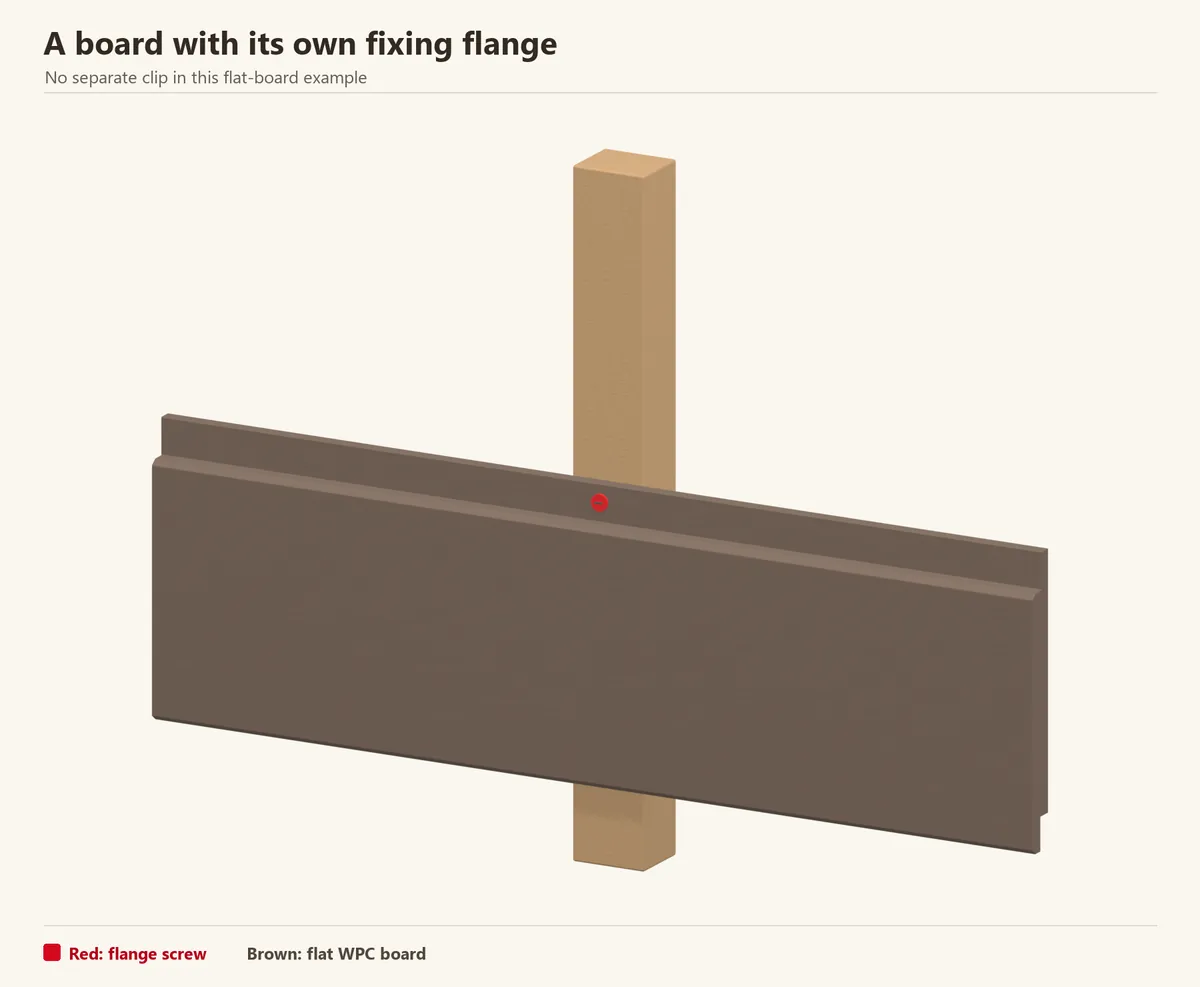
The worked example is a flange-fixed WPC profile. A screw passes through the thin upper fixing edge into a batten. The next board engages over that edge and hides the screw. There is no separate metal clip between these courses.
EnviroBuild’s Explorer instructions include a rail-free starting option. Use that option only with a profile whose manual permits it. The illustrations explain the arrangement; they are not manufacturing drawings or a fastening schedule.
Reference: EnviroBuild — Explorer and other composite cladding installation manuals
Step 1 of 11
Prepare and weatherproof the wall
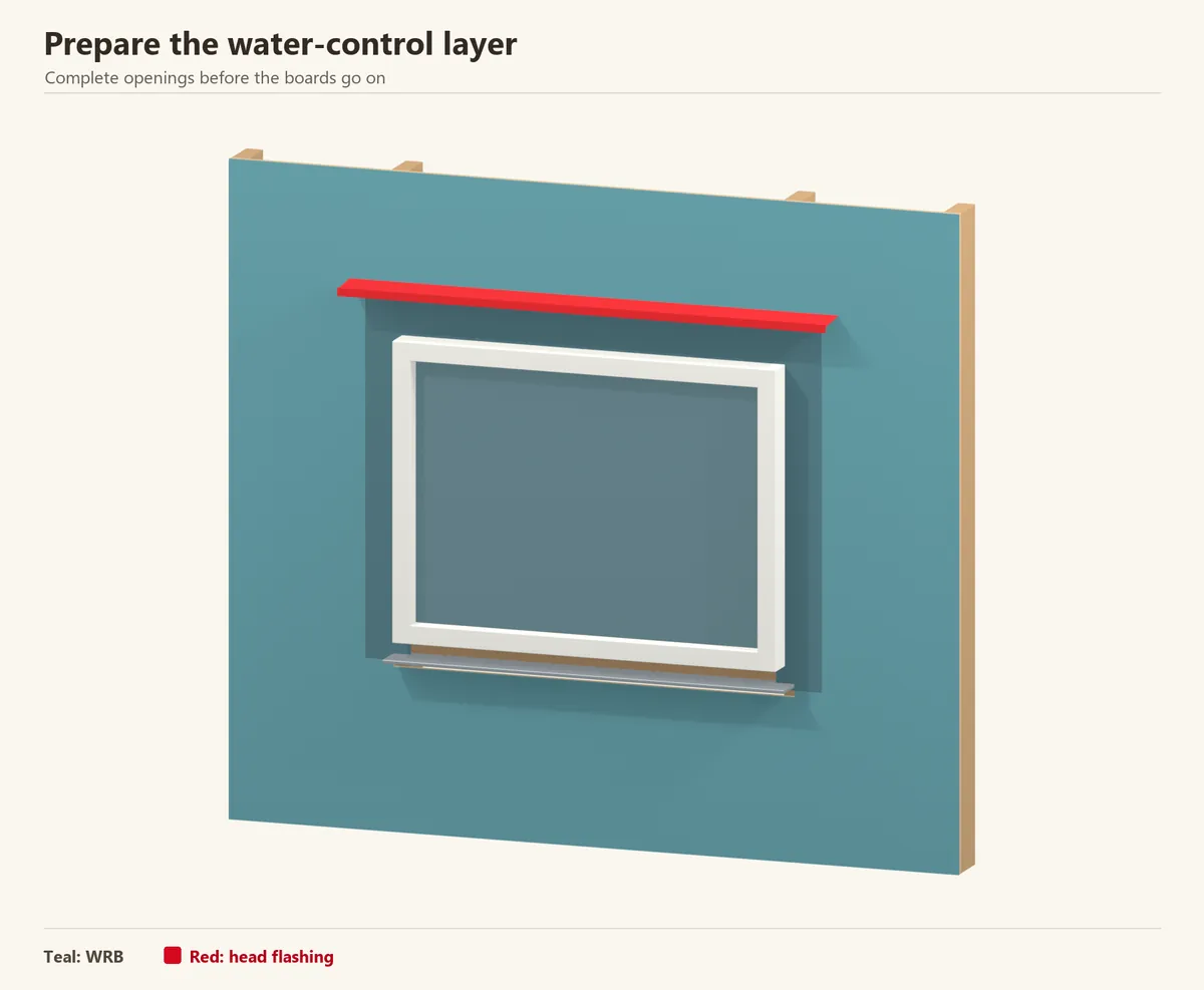
Start with a sound, flat shed wall. Fix loose sheathing and mark the structure that will receive the batten fixings. Work around all four elevations before covering anything; an unsupported corner is easier to correct now.
Complete the weather barrier and the window and door flashings in the order required by those systems. Overlaps must lead water down and out. Take photographs of the finished backing before it disappears behind cladding.
Check before continuing: The wall is weatherproofed and support positions are marked.
Reference: DuPont — weather barrier and opening flashing instructions
Step 2 of 11
Fit the vertical battens
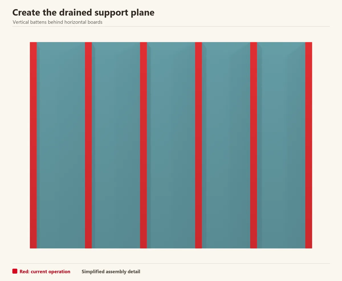
Set the battens in one flat plane, checking across several supports with a long straightedge. Add support for board ends and perimeter trims instead of relying on the cladding to hold adjacent pieces.
The referenced flange-fixed system calls for a cavity of at least 38 mm. Choose batten spacing and structural connections from its current manual and your wall design; decorative trim screws are not a substitute for those connections.
Check before continuing: Every planned board end and trim fixing has backing.
Reference: EnviroBuild — Explorer and other composite cladding installation manuals
Step 3 of 11
Keep the base clear and drained
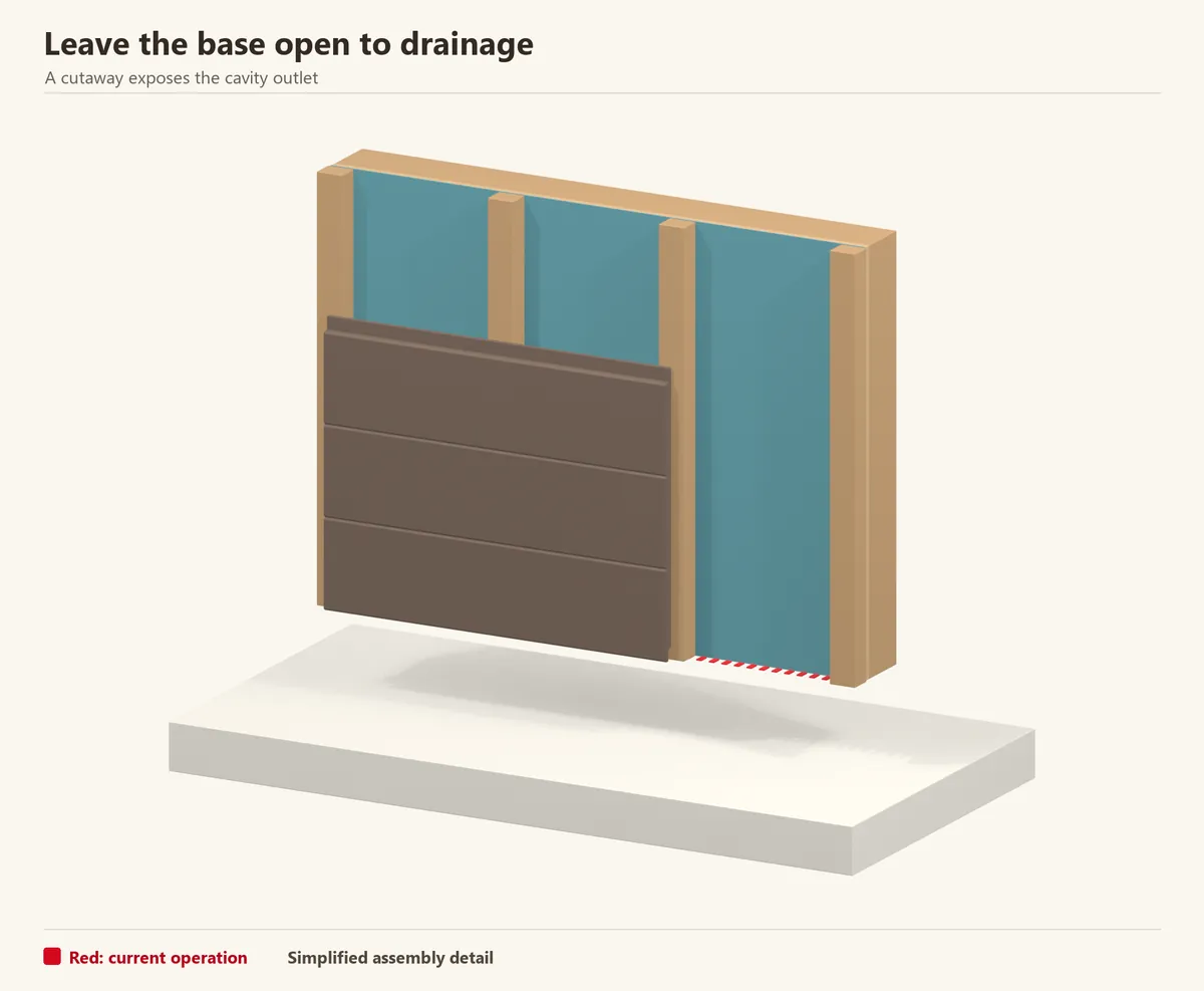
Establish the lowest course from a level datum, then check it against the highest point of the surrounding ground or paving. A level shed can still stand beside sloping ground.
Keep the cavity outlet clear and fit a ventilated insect closure where specified. The drawing leaves part of the cladding off so you can see the outlet. Set the actual soil, paving and roof clearances from the selected system and site detail.
Check before continuing: Neither the lowest board nor its cavity will be buried by the finished surface.
Step 4 of 11
Set the first board level
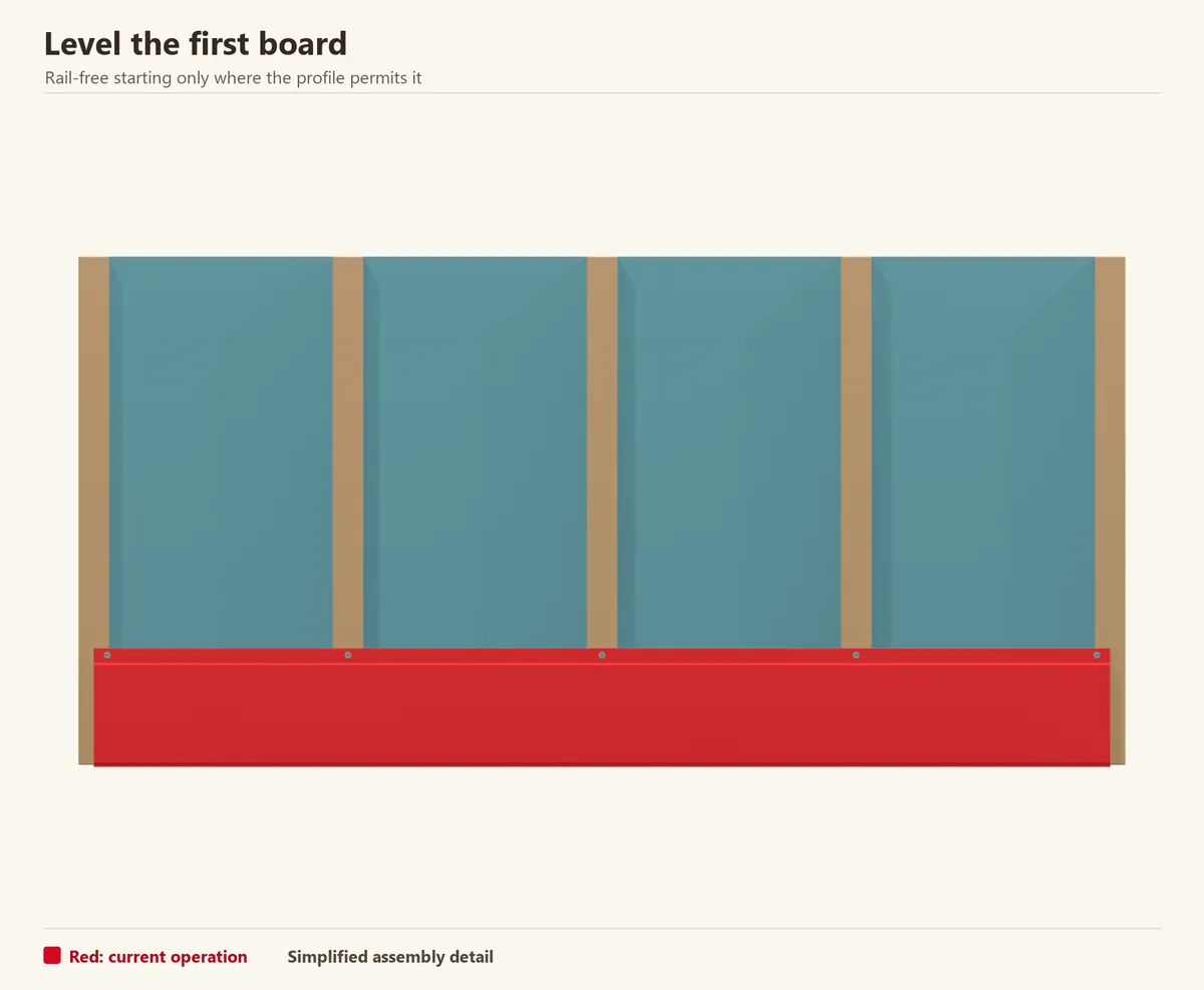
Measure between the finished corner or end details, allowing the required movement space. Make the first cut on a spare piece to check the saw setting, then prepare the board for the wall.
For the illustrated rail-free option, position the first board on the marked datum and secure its upper fixing flange. Recheck the line at both ends before progressing. If your profile requires a starter rail, install that matching rail first.
Check before continuing: The first board establishes a level line around the shed.
Reference: EnviroBuild — Explorer and other composite cladding installation manuals
Step 5 of 11
Engage the next board
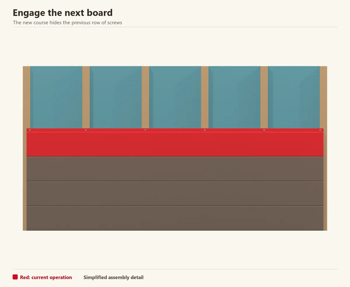
Offer the next board to the installed course and engage its lower edge along the full length. Work steadily across the wall so one end does not rise while the other is seated.
Look along the joint before fixing. Clear chips from the interlock and replace damaged pieces; forcing a poor fit can leave a visible step that repeats in every course above it.
Check before continuing: The new course sits evenly and covers the previous fixing edge.
Step 6 of 11
Predrill and screw through the flange
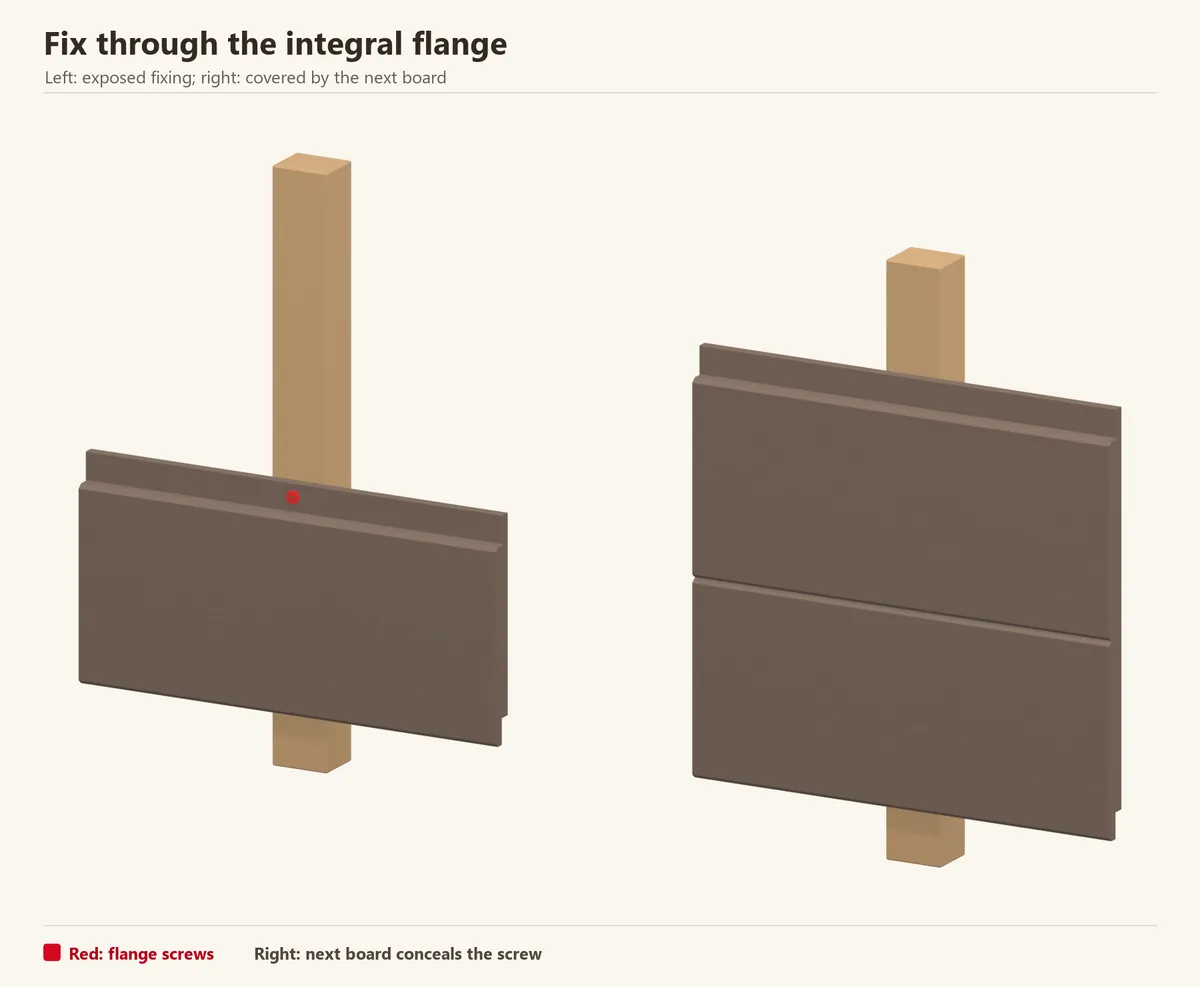
Fix through the designated channel at each support. In the referenced example, 7 mm clearance holes work with 10 mm flanged screw heads; the screws must not be overtightened. These dimensions belong to that system, not every composite board.
The close-up shows the same joint before and after the next board covers it. Use the prescribed screw and hole detail throughout, including the short pieces around a window.
Check before continuing: The flange is secure and retains the movement the fixing detail allows.
Reference: EnviroBuild — Explorer and other composite cladding installation manuals
Step 7 of 11
Continue with supported end joints
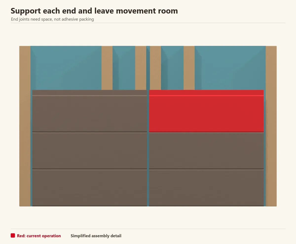
Plan the joints on paper before cutting the remaining boards. On a small wall, a full-length piece may avoid a joint altogether. Where two pieces meet, arrange backing for each end and keep the prescribed gap open.
Measure the actual board length and use the maker’s movement allowances. Do not pack a visible gap with adhesive to make it disappear; use the approved cover arrangement if the design calls for one. Check course heights at the corners as you work.
Check before continuing: Both ends are supported without closing their movement space.
Step 8 of 11
Cut around the flashed openings
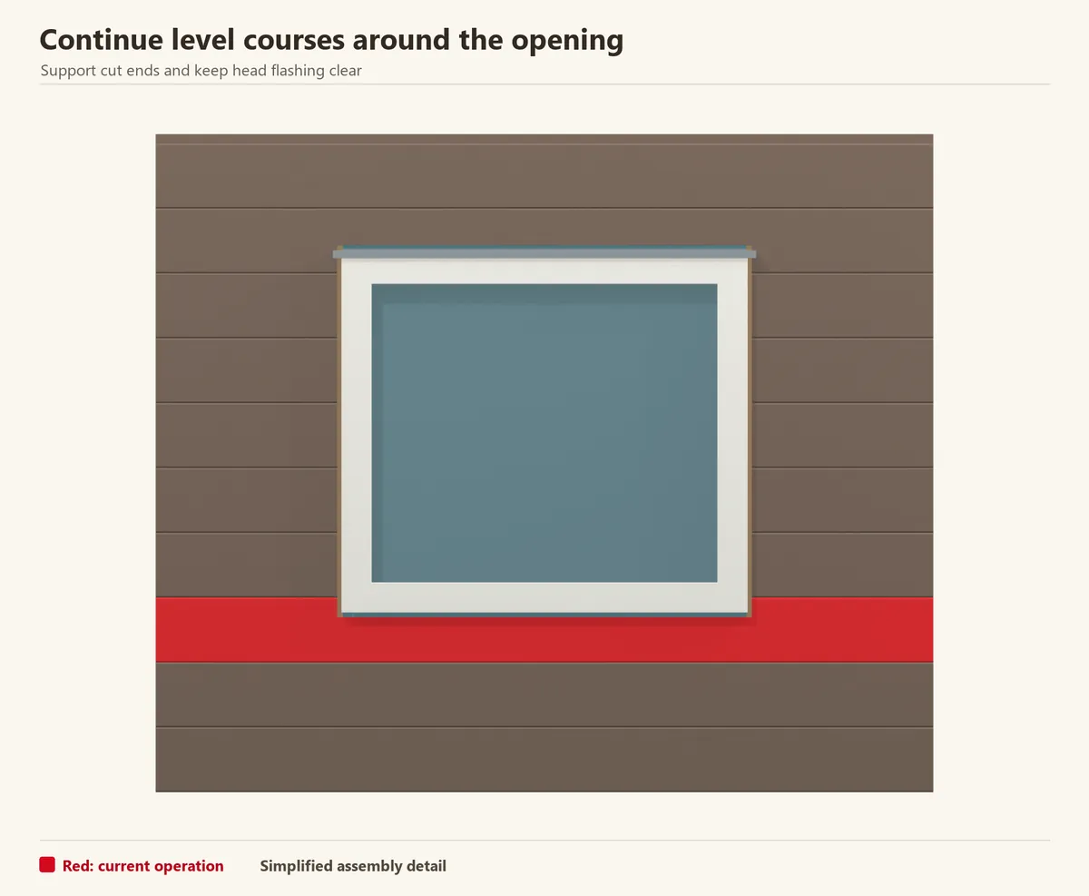
Carry the same course lines across both sides of the opening. Mark the notch on the board, test the fit and support each remaining end. Avoid making a narrow piece carry the weight of a trim.
Keep the head flashing clear above the window. The drawing shows one cladding layer and an aligned cut course, with the casing already fitted. Coordinate the cladding clearance with the window’s drainage detail.
Check before continuing: The courses align and the head flashing can discharge water.
Reference: DuPont — weather barrier and opening flashing instructions
Step 9 of 11
Fit the corner covers
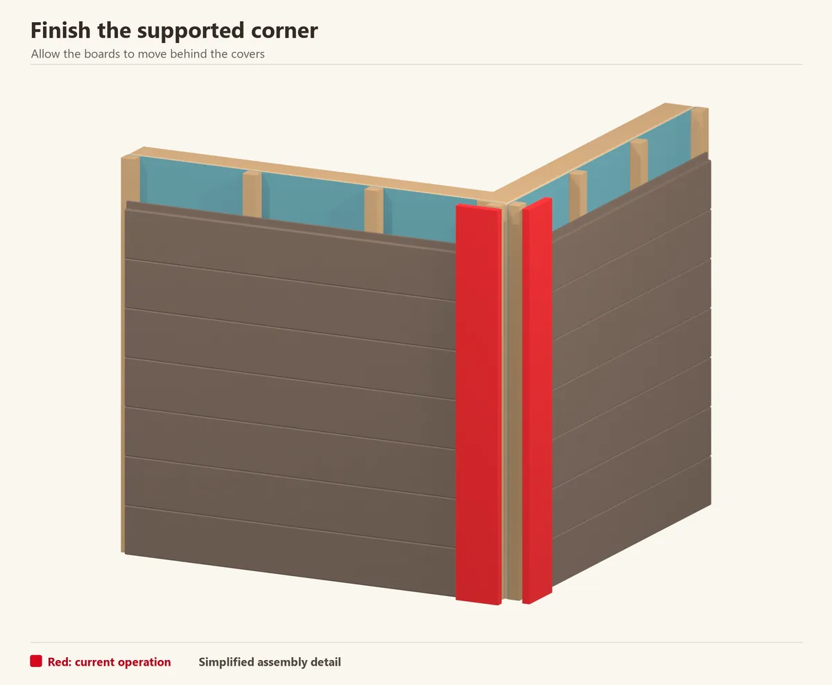
Check whether your corner accessory goes on before or after the boards. Install it at the specified stage and fix into its own backing. Sight down the corner from both faces to check it is straight.
The cover should hide the cut ends while preserving their allowance. Keep the same visible course height on the adjoining wall; a neat corner cannot hide a drifting layout.
Check before continuing: The corner is straight and its cover does not clamp the board ends.
Step 10 of 11
Cover the final fixing edge
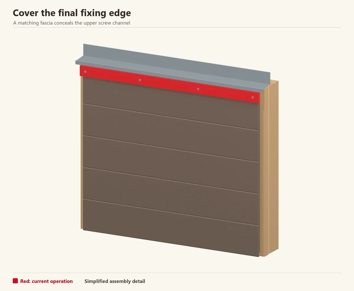
Plan the remaining height so the last board can retain its fixing channel. The referenced finish covers that channel with a matching fascia, secured through prepared holes. Keep the top clearance and ventilation open.
Measure at several points before making the final cuts. If the wall height would remove the fixing channel, obtain the profile’s approved cut-board termination detail instead of improvising a row of nails or relying on adhesive.
Check before continuing: The final fixing edge is covered and the top clearance stays open.
Reference: EnviroBuild — Explorer and other composite cladding installation manuals
Step 11 of 11
Clean and inspect the wall
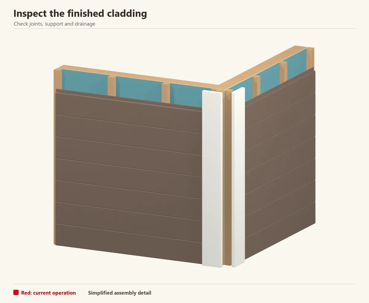
Remove chips and temporary marks using the surface maker’s care instructions. Inspect the base, every opening, both faces of each corner and the top termination in daylight.
Keep a labelled offcut and a small supply of the correct fasteners. Record the product and colour with your shed paperwork so future repairs do not depend on matching a weathered board by eye.
Check before continuing: Trims are secure, movement spaces are clear and water can leave the wall.
Other composites use clips—or permit nails
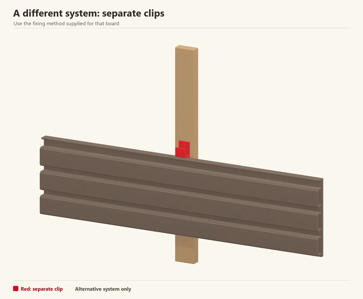
The alternative drawing shows a separate clip engaging a ribbed board. NewTechWood’s European system uses this kind of dedicated hardware, with its own attachment and locking instructions. Those parts do not belong in the flange-fixed sequence above.
Some other composite families, including Everlast, permit approved nails or screws through a nailing hem. That does not make ordinary nails suitable for the WPC board shown here. Identify the actual profile, then use its fixing instructions.
Reference: NewTechWood — horizontal clip-fixed European siding instructions (PDF) · Everlast — installation resources for its separate composite system
Common questions
Does all composite cladding need metal clips?
No. Some boards have an integral flange that takes screws; others use separate clips. This guide’s main sequence shows the flange-fixed method.
Can I nail WPC boards straight to the shed?
Only use nails where the exact product instructions permit them. The flat WPC example here uses screws into battens, with a drained cavity and movement allowances.
Is the installation as simple as fitting the boards?
The repeating board sequence is straightforward once the backing, flashing, starting line and trims are ready. Most of the planning is at the base, openings, corners and final course.
Installation references
Sources checked 24 October 2026. Use the current instructions for your product and region when purchasing and installing.