
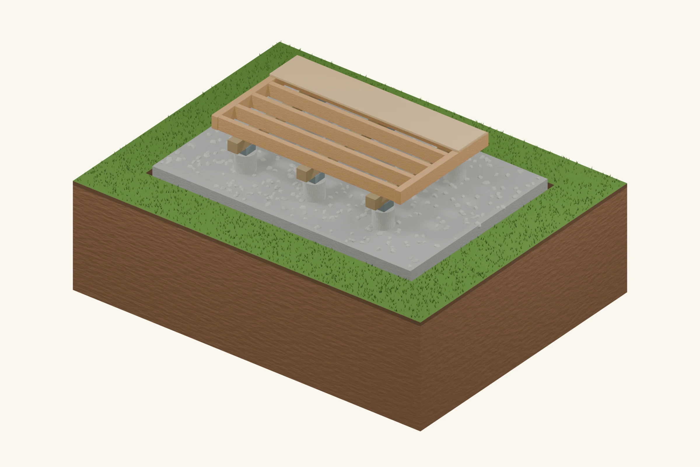
Piers are useful when a timber floor needs discrete permanent supports, particularly where a level gravel platform would be awkward. The pier shaft, footing, beam and connector form one load path. Depth alone does not prove adequacy: the footing also needs sufficient bearing area, the exposed portion needs stability, and uplift and sideways forces must reach the ground.
Is it right for your shed?
Best fit: Raised timber floors on sites requiring designed deep supports or controlled elevation changes.
Advantages
- Can follow a sloping site without filling the whole footprint.
- Keeps the floor structure above the ground.
- A designed footing can reach suitable bearing below weak surface layers.
Limitations
- Excavation and inspection can be demanding.
- Concrete and hardware placement require accurate layout.
- Tall exposed piers and posts need lateral design.
What goes under it? The ground layers
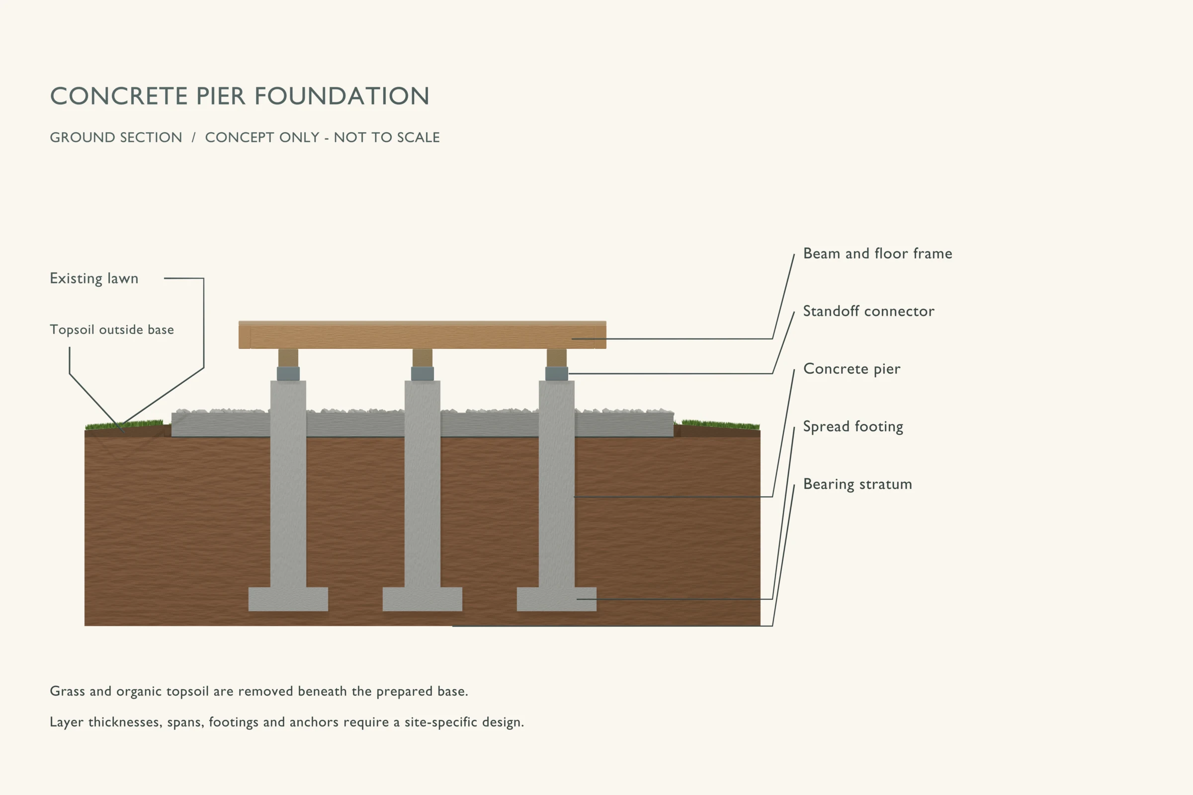
The explanation runs from the ground upward. Callout labels in the drawing identify the visible parts; some thin layers are enlarged for clarity.
- 1
Competent bearing stratum
The footing bears on accepted soil at the specified elevation.
- 2
Spread footing
Its area spreads the column load; diameter is a bearing-design decision.
- 3
Concrete pier
The shaft carries loads between footing and connector, with reinforcement as designed.
- 4
Standoff connector
Rated hardware separates timber from concrete and transfers specified forces.
- 5
Beam and floor
Beam joints and spans follow the support layout; connections continue the load path.
Materials and preparation
Use the quantities and specifications from your actual layout. Before ordering, resolve the pad footprint, support locations, finished floor height and the drainage route.
- Designed footing/pier schedule and specified reinforcement
- Concrete, approved forms and rated beam or post connectors
- Excavation equipment, braces and survey/level tools
Useful planning: choose the shed location and check permit requirements.
Build sequence
This sequence explains the order of work. Use it alongside the foundation design and the instructions for your chosen products.
Step 01
Lay out from the beam design
Mark centers using offset strings that survive excavation. Establish top-of-pier elevations and check that beam splices land where the design expects support.
Step 02
Excavate and verify bearing
Locate underground services first. Excavate to the approved depth and bearing material. Keep people out of unsupported excavations and arrange required inspection before covering the bottom with concrete.
Step 03
Form footings and shafts
Install forms and reinforcement with the required cover and support. Do not use a pile of loose stones as a substitute for a designed footing or reinforcement chair.
Step 04
Place concrete and connectors
Follow the concrete specification and connector installation instructions. Brace templates so anchors stay aligned. Use only approved cast-in or post-installed anchors; their capacities and edge distances differ.
Step 05
Cure before loading
Protect and cure the concrete, then load it only when the required strength has been achieved. Install beams, bracing and floor connections, and backfill as specified without damaging the piers.
Mistakes to avoid
- Treating the frost depth as the only design dimension.
- Setting every pier at the local ground height rather than the required beam level.
- Using an ordinary post base as if it fixes a tall unbraced column against rotation.
Inspection and maintenance
Inspect for soil erosion, widening concrete cracks, corroding connections and out-of-plumb supports. Keep water from concentrating around shafts. New movement is a reason to investigate bearing and stability rather than merely adjusting the door.
When to choose a different base
Compare piers with skids when the site slopes or permanent supports are needed. Compare a slab when the intended floor is concrete; a pier-supported wood floor is not automatically suitable for vehicle loads.
Common questions
How deep and wide should the piers be?
Use the site design: frost requirements, bearing stratum, soil capacity, loads and uplift all matter. The illustration intentionally gives no universal diameter or depth.
Are concrete piers frost-proof?
Only when designed and installed with the required frost protection, bearing and resistance to relevant ground forces. A shallow concrete cylinder is still a shallow support.
Technical references
Use the currently adopted local requirements and the exact product instructions for your build. These references explain the principles behind this guide.
- ICC: 2024 IRC, Chapter 4 — Foundations
Model-code background for bearing and frost protection. Your adopted code and local amendments control.
- NRMCA: Concrete in Practice
Concrete placement, joints and curing; see CIP 6 and CIP 11.